REPAIR AND RESTORATION OF THE SR-400
13
WDØGOF 6/22/20014
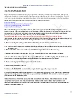
3. TRANSMITTER TESTING
At the start of the receiver testing you replaced the power supply fuse with a 4 amp normal delay. It is time to
re-insert the 5 amp slo-blow fuse. The goal of this section is
not
to get maximum power out of the radio. The
goal is simply to prove that the major transmitter sections are functioning. For now 100 watts or better is good.
CAUTION: FATAL VOLTAGES ARE OPEN AND EXPOSED ONCE THE COVERS OR CASE IS
REMOVED. OBSERVE THE FREE HAND RULE. THAT IS, ANY TIME THE POWER IS APPLIED, IF
YOU ARE RIGHT HANDED YOUR LEFT HAND IS IN YOUR HIP POCKET. IF YOU ARE LEFT
HANDED YOUR RIGHT HAND IS IN YOUR HIP POCKET
MAJOR KEY POINT
, the transmitter testing process
assumes
that the receiver has been tested and is
operating to specs.
3-1. TEST EQUIPMENT REQUIRED
500 watt wattmeter & dummy load
100 MHz scope
Frequency counter
Audio oscillator with 600 ohm output
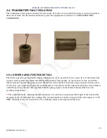
Driver capacitive pickup (home brew item see figure section )
600 ohm dynamic mic
Multimeter 2 VDC full-scale and 10 VDC full-scale recommended
Optional
telegraph key
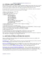
3-2. STANDARD TEST CONDITIONS
You will start with the following control settings
OPERATION
MOX
FUNCTION
LSB
CAL
OFF
CAL ADJ
MID RANGE
MAIN TUNING
7.3MHZ
CW filter
OFF
NOTCH
CCW
BAND SELECTOR 7.0
PRESELECTOR
40
AF GAIN
MIN
RF GAIN
MIN
NOISE BLANKER OFF
METER
RFO/S
RF LEVEL
CCW
MIC GAIN
CCW
RIT
OFF
RIT CONTROL
MID RANGE
LOAD & PLATE
PRESET TO VALUES ON CHART ON PAGE 20 OR 21 OF MANUAL
Wattmeter and load connected to J1.

