REPAIR AND RESTORATION OF THE SR-400
14
WDØGOF 6/22/20014
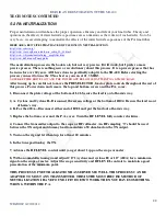
3-3. BIAS ADJUST
(plate idle current adjustment)
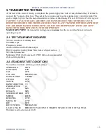
With the power off plug your meter into the test jacks on the power supply c to the red jack – to the blue
jack.
CAUTION the meter leads will be attached to the PA high voltage, fatal shock hazard is present.
Insure the front panel settings are in accordance with paragraph
3-2
then power up. Allow 15 minutes for tubes
to get to full operating temperature. Install microphone. Key mic and adjust the BIAS ADJ on the front panel
for a reading of 0.7 volts dc on the meter. This equates to an idle current of 70 mills of plate current.
Always
use this method to test and adjust the plate idle current. The front panel plate current readings are not accurate
enough to properly set the idle current.
The next series of tests will be conducted in the MOX, CW mode. You will need to switch the FUNCTION
switch from LSB to CW quite often. You MUST keep the transmit duty cycle short. I find it easier to plug a key
into the key jack on the rear of the transceiver. Then you can set the FUNCTION switch to the CW position and
leave it there and press the key when you want power. This saves wear and tear on the FUNCTION switch and
reduces the chances of leaving the transmitter keyed to long. For the remainder of the tests when you are
instructed to “
key the transmitter
” you will either switch the FUNCTION switch from LSB to CW or press the
key.
3-4 INITIAL TRANSMITTER TESTS
Reset all controls as stated in section 3-2
3-4-1 TRANSMITTER POWER TEST
The following tests are preliminary test to assess the overall transmitter performance. One hundred watts is
sufficient at this point.
Set the meter that is plugged into the power supply to the 10 vdc full scale range. Set the RF LEVEL to 5. In the
next series of tests monitor the plate current via the meter plugged into the power supply. One volt equals 100
mills of plate current.
Keep adjusting the RF LEVEL to keep the plate current below 200 mills.
Keep the
duty cycle short. Power up and allow 5 minutes warm up. Key the transmitter in the CW mode. Peak the plate
current with the PRESELECTOR. Peak the plate current with L10, L33 and LOAD. Tune the PLATE for a dip
in plate current which should coincide with a peak in power output. If the plate current dip and the power output
peak do not coincide it indicates the PA needs neutralization. You will address this later. But for now remember
to
keep the duty cycle very short
until you get it neutralized.
Set the band switch to 3.5, key the transmitter and adjust the PRESELECTOR, L11, L34 and LOAD for max
plate current, and dip the PLATE. Temporarily advance the RF LEVEL and record the max power out.
Set the band switch to 14, key the transmitter and adjust the PRESELECTOR, L9, L32 and LOAD for max
plate current, and dip the PLATE. Temporarily advance the RF LEVEL and record the max power out.
Set the band switch to 21, key the transmitter and adjust the PRESELECTOR, L8, L31 and LOAD for max
plate current, and dip the PLATE. Temporarily advance the RF LEVEL and record the max power out.
Set the band switch to 28.5, key the transmitter and adjust the PRESELECTOR, L7, L30 and LOAD for max
plate current, and dip the PLATE. Temporarily advance the RF LEVEL and record the max power out.
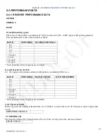
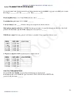
If you achieved 100 watts on all bands (50 watts on10 meters) proceed to section 4-2 PA NEUTRALIZATION.
When the neutralization is complete it is time to move on to a complete alignment. Some of the alignment has
already been completed. You will need to complete the following steps in the manual: 8-5 and 8-9 through 8-12.
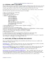
If the minimum power is not achieved proceed to section 3-5 the TRANSMITTER FAULT ISOLATION. Once
you get the transmitter working then return to the beginning of 3-4-1 and proceed from there.

