REPAIR AND RESTORATION OF THE SR-400
15
WDØGOF 6/22/20014
3-5, TRANSMITTER FAULT ISOLATION
The assumption at this point is that the receiver works. If it does not you need to back up to section 2 and clear
the receiver faults. For the fault isolation tests preset the equipment as listed in 3-2. STANDARD TEST
CONDITIONS.
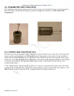
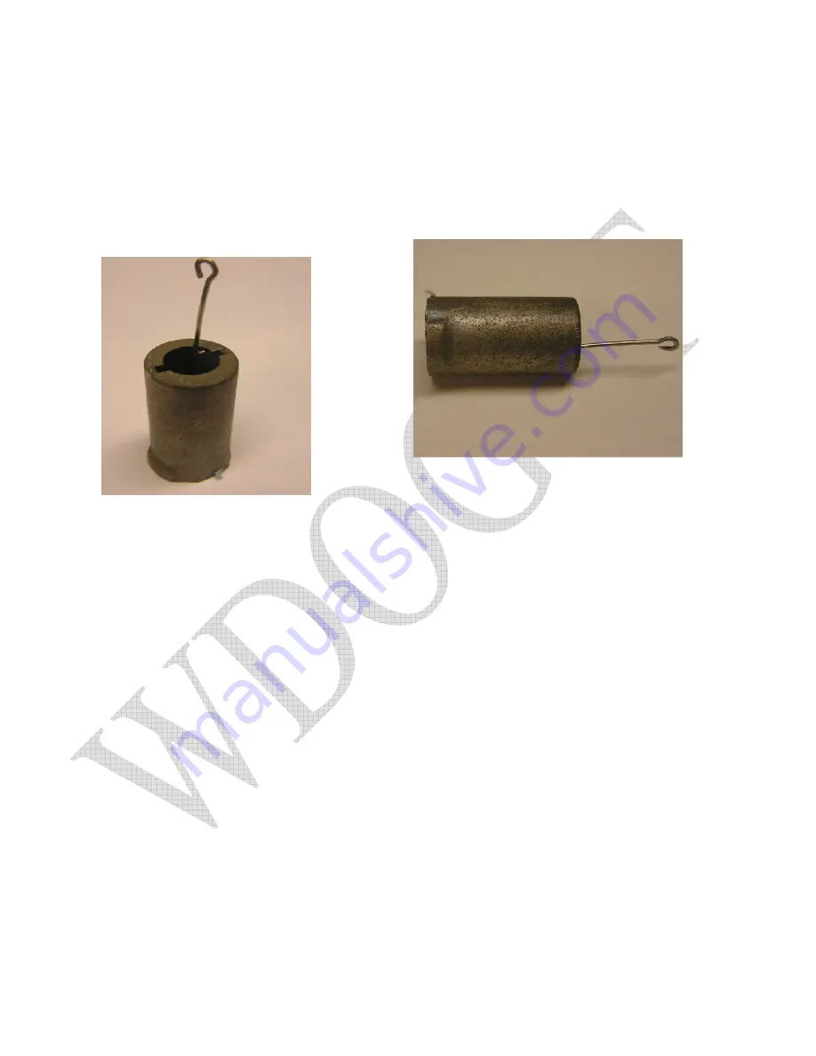
3-5-1, DRIVER CAPACITIVE PICKUP TOOL
The driver capacitive pickup tool is simply a metal sleeve. It is constructed to be a close fit over the driver tube
in place of the normal tube shield and NOT making contact with ground. As shown above I took an old tube
shield, removed the internal spring and cut off the base of the shield. I then bent a large loop one end of a piece
of buss wire, just a little larger than the inside diameter of the shield. On the other end of the buss wire I formed
a small loop. Using the tabs that originally held the spring in place in the shield, I mounted the buss wire
assembly in the shield
**
The amplitude of the sampling depends upon how you construct your pickup. The length of the tube and the
closeness of the fit will affect the coupling. The one pictured above shows 40 vpp for 200 watts output at 3.900
MHz. You will need to test your device on a working system to develop the norms for it.

