REPAIR AND RESTORATION OF THE SR-400
16
WDØGOF 6/22/20014
3-5-2, LOW OR NO POWER ACROSS ALL BANDS
A. Set the band switch to 3.5 and the main tuning to 3.9MHZ. Set the PRESELECTOR near the upper end of
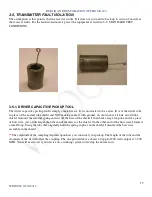
the 80 meter band. Power up and warm up. Remove the shield from V18 and install the DRIVER
CAPACITIVE PICK UP tool. Connect the scope to the pick-up tool. Key the transmitter, peek the
PRESELECTOR, L11 and L34. If you have
**
40 vpp on the scope, unkey the transmitter. Move the probe from
the scope to the frequency counter, key the transmitter. You should get 3.9MHZ on the counter. Unkey the
transmitter. If you have 3.9MHZ at
**
40 vpp or better and there is no or low power out, your problem is in the
PA. If not go to step B.
B. Connect the 10:1 scope probe to pin 2 of V18. NOTE: as soon as you connect the probe to the tie-point you
will detune the ckt. Some adjustment of L11 may be required to peak the signal. Key the transmitter advance
the RF LEVEL control to 7 and peak L11. A signal level of 5 vpp should produce 200 watts. If you have 5 vpp
and still no power out the problem is in the driver or associated circuitry. If the signal is incorrect go to step C.
C. If the signal is not correct connect the probe to pin 7 of V11. Pull V2. Key the transmitter; you should see 4
vpp on the scope. If the signal is correct go to step D. If it is not, and since the receiver is working properly, the
problem is in the Het Osc transmitter switching circuit. Check the dc voltage on the tie point of L20 and the
cathode of CR11. It should be greater than 14 volts in receive mode and less than 1.9 volts in transmit mode. If
this voltage is correct then either CR11 or C47 is bad. The voltage on the cathode of CR11 is developed by the
cathode current of V15 (the audio output tube). If the voltage on the cathode of CR11 does not drop in transmit
mode check the grid of V15. The grid should go to gnd in transmit mode, if it does not check relay K2. If the
voltage is not correct in receive mode measure the voltage on the opposite end of L20. If the voltage is good
then L20 is bad.
D. Reinstall V2 and remove V12. Connect the scope to pin 7 of V11. Key the transmitter. You should have 3.5
vpp. If the signal is correct, and the test B above was good, then the fault is in V11 and its associated circuitry.
E. If the signal is not good, reinstall V12 and move the scope to pin 7 of V2 (VFO signal injection). Key the
transmitter and you should have 3.5vpp. If the signal is not correct the fault is most likely CR34 or V2.
F. If the signal is good move the scope to V2 pin 2(carrier/balanced mod injection signal). Key the transmitter.
If the signal is 0.6 vpp the fault is most likely in V2, or its associated circuitry.
Note:
Here again since you have
proven that the receiver is functioning properly you can eliminate T1, T2 and V3 as a cause.
G. If the signal is not good move the probe to V6 pin 1. Key the transmitter. The signal should be 1 vpp. If the
signal is good then the fault is most likely the alignment of L15 and L16. If the signal is not good the fault is in
the balanced modulator T6 and its associated circuitry.
This completes the transmitter fault isolation process. You should have found the fault at this point. If not then
verify that the receiver is functioning properly. Then restart section 3 test procedures. There are many circuits
that are used in both RX and TX, by verifying the RX functions you are also proofing all the common ckts.
3-5-3, NO OR LOW POWER ON A SINGLE BAND.
Select the affected band and follow the procedure in
3-5-2.
Eliminate the common components and concentrate
only on the switches and switched components. Go back and review the results of tests in
1-5-3
(het osc tests).

