REPAIR AND RESTORATION OF THE SR-400
17
WDØGOF 6/22/20014
4. SUBSYSTEM TROUBLESHOOTING AND TESTING
4-1 VFO DRIFT
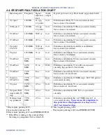
You have performed all the tests in section 1-5-4 and determined that you have a drift problem. Perform the
drift test in receive, LSB mode. Then perform the same test in receive, USB mode. If you have the drift problem
in USB but not LSB the most likely cause is CR12, C126 or C127. A bad ground on C127 could also be a
source of trouble. If you determine the drift is the same in LSB and USB just about any of the N or NPO
capacitors inside the VFO enclosure could be suspect. Grounding particularly on C120 and C122 could also be
the source. You can either shotgun the VFO and replace all the caps or replace them one at a time until you find
the bad one. In many cases more than one is contributing to the failure.
4-2. V15 RX FAULT ISOLATION
Turn the power 0ff. Disconnect the power supply. Pull V15. Inject 1000 Hz at 20 vpp into pin 5 of the V15
socket. Connect J5 (AUDIO 500 ohm phono jack on rear of chassis) to the scope. If you get 15 vpp at J5 the
output transformer and associated circuitry are good. If it failed step 1 in the RECEIVER FAULT ISOLATION
CHART then V15 or its associated circuitry is at fault.
4-3. V9B RX FAULT ISOLATION
This circuit is pretty straight forward. Check the voltages and resistances against the charts in the manual. If
they are correct then the options are few. C78, C77 or R48 are the most likely cause of the fault.
4-4. V9A RX FAULT ISOLATION
Power up and set the standard test conditions. In LSB mode you should have a 6 vpp signal on pin 8 of V9A.
Move the probe from the scope to the frequency counter. You should see 1650 KHz on the counter. If you do
not get the proper level of signal on frequency then the fault is likely in the BFO/Carrier oscillator or C138.
4-5. V7A RX FAULT ISOLATION
Perform the voltage and resistance test per the charts in the manual for V7. If the voltages and resistances are
good then the likely cause of the fault is; V7A, C8, C60, C71, C72 or T3.
4-6. XTAL RX FILTER/NOTCH FAULT ISOLATION
Lift the lead of C61 that connects to Y12. Into the lifted lead of C61 inject 1500 uv of 1650 KHz you should get
½ watt of audio out. If you get ½ watt of audio then the fault is in the Y12/CR23 bias or switching networks.
Reconnect C61. If you do not get the ½ watt audio move the injection probe to the output side of the filter.
Reduce the level of injection to 500 uv. If you get ½ watt audio output then the filter is bad. If you do not get
proper audio out then L16, R169, C228 or Y13 and its associated bias and switching network are at fault.
4-7. V6 RX FAULT ISOLATION
NOTE: In this next step you will be injecting signal into the plate pin of the tube socket. If your probe is
NOT D.C. blocking and not rated for 300 vdc or higher you WILL DESTROY the attenuator in your
signal generator. You will need to acquire or construct an injection probe that will handle that voltage
.
Pull V6, power up and inject 3000 uv at 1650 KHz into pin 5 of the V6 socket. If you do not get at least ½ watt
audio out then L5, C54, C59 or C182 is at fault. If you get ½ watt then V6 or associated circuitry are at fault. If
the tube is known to be good then refer to the voltage and resistance charts in the manual. If the voltages and
resistances are correct then suspect C55, C56, C57 or C245. If all this checks ok then pull V5 and repeat step 6
in the RX FAULT ISOLATION chart (Paragraph
2-4
). If you get ½ watt audio out then V5 or its associated
circuitry are at fault.

