REPAIR AND RESTORATION OF THE SR-400
19
WDØGOF 6/22/20014
5. TECH NOTES
5-1. BASIC TUNE UP
The RF power out and PLATE current monitoring leaves a little to be desired in the SR-150 through the SR-
500. This short fall was corrected in the SR-2000 with the addition of a dedicated plate current meter in the
power supply.
5-1-1. THE PROBLEM:
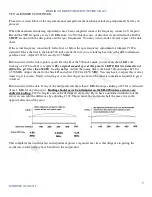
During PA tune up the RF power out peak and the plate current dip (
true resonance
point) do not always
coincide. Proper tuning should always be to the plate current dip. To accomplish this the way the equipment is
designed requires constantly switching the meter switch on the 400 from RFO to PLATE MA. Proper
neutralization of the PA finals will minimize this effect. Regardless of how well the equipment is neutralized
differences in the power peak and the plate current dip will occur across the bands.
5-1-2. WHY IS THIS IMPORTANT?
At
true resonance
the PA tubes are operating at their most efficient point, and this adds to the life of the tubes.
At
true resonance
spurs and harmonics are at minimum.
At
true resonance
components in the plate circuit are under minimum stress (very important in the SR-150).
At
true resonance
you rig just sounds better.
5-1-3. A SIMPLE SOLUTION.
Plug an external meter into the test jacks in the power supply and leave it there as a permanent monitor.
Commonly one of the jacks is red the other is blue. CAUTION the meter leads will have the plate voltage
present at all times. The meter should be set to the 10vdc full scale range, red lead to the red jack and black lead
to the blue jack. Then you can leave the meter switch in the RFO S position during tune up and operation. The
only time you will need to change the meter switch is when checking AALC.
5-1-4. SUMMATION:
This simple meter addition not only simplifies tune up but adds a constant critical monitor to your system. Any
problem in the PA, transmission lines or the antenna are immediately reflected in the plate current.

