REPAIR AND RESTORATION OF THE SR-400
21
WDØGOF 6/22/20014
TECH NOTES CONTINUED
BASIC TUNE UP CONTINUED
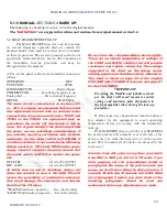
C. Set the OPERATION control to MOX. The idle
plate current of the final amplifier stage should
indicate less than 100 milliamperes. If 100 ma is
exceeded immediately return to REC mode. Check to
see that the RF LEVEL control is set to zero and the
BIAS ADJ control on the power supply is set at its
full clockwise position for maximum bias voltage
There are two versions of the PS-500 power
supplies. The early version was produced to
work with the SR-500 and the SR-400 Cyclone.
This power supply has a potentiometer on the
rear of its chassis used to set the BIAS for the
SR-500. Many of these power supplies have
been reworked and may have the BIAS pot
wired in reverse. To be sure of the setting of
this pot unplug the power supply from the
power source and the R/T unit. Connect an
ohmmeter from pin 4 to pin 3 of J201. Set the
pot for maximum resistance. With the meter
positive lead on pin 3 and the negative lead on
pin 4 it should read greater than 30k ohms.
The later version of the PS-500 did not have
the pot for BIAS ADJ but, has an AC receptacle
to provide power to a cooling fan.
After making the no power checks and
adjustments proceed to section 8-3 and insure
that proper idle current can be achieved. If
normal function cannot be achieved, this fault
must be cleared before proceeding.
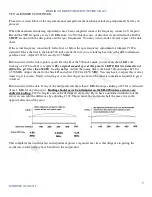
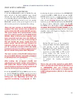
D. Set the METER selector at RFO/S and check to
see that the PLATE and LOAD controls are preset
per the tuning chart.
NOTE: The METER selector
setting will vary depending upon how you
approach monitoring in paragraph B.
While
monitoring the plate current move the OPERATION
control from REC to MOX. Slowly increase the RF
LEVEL until you see a slight increase in plate
current. Now adjust the PRESELECTOR for max
plate current.
Caution:
Monitor the plate current
and if it exceeds 300 mills back off on the RF LEVEL
to keep it below 300 mills. Adjust the PLATE
CONTROL for a dip in plate current.
REMEMBER
TO KEEP THE TX DUTY CYCLE SHORT.
At this
point you have reached resonance however, the final
amplifier stage still requires a loading check and
possible adjustment.
NOTE
During the next step of the transmitter
tuning procedure the final amplifier tubes
will operate at their highest plate
dissipation. The plate dissipation at this
time will be higher than for continuous
operation on either SSB or CW at full
power output. For this reason it is
recommended that full carrier power be
applied only for the length of time needed
to evaluate the loading adjustment
required.
This is the end of this marked up guide. BUT,
this is not the end of the tune-up procedure. It
is IMPERATIVE that you continue with
paragraph E, of the manual to complete the
LOAD tuning procedure. Return to the original
manual.

