REPAIR AND RESTORATION OF THE SR-400
9
WDØGOF 6/22/20014
VFO ALIGNMENT CONTINUED:
Proceed to section 8-8-A of the original manual and perform the mechanical indexing adjustments before you
proceed.
When the mechanical indexing adjustments have been completed connect the frequency counter to V4A pin 3.
Record the VFO frequency every 100 KHz from 0 to 500 (black scale). A data sheet is provided in the DATA
SHEET section with the data points and the spec frequencies. You may want to make several copies of the data
sheet.
If the actual frequency consistently falls above or below the spec frequency adjustment of trimmer C122 is
indicated. Move the dial to the black 500 index mark (be sure you are looking head on at the dial to eliminate
parallax error). Adjust C122 for exactly 4.35 MHZ.
Rerun and record the 6 data points again. If at the Ø or the 500 index mark you are more than 1 KHz off,
tracking of C122 and L21 is required.
The original manual spec at this point is 2 KHZ. But it is normally not
difficult to get it less than 500 Hz. So why not try.
Adjust the tuning dial to the black 500 and adjust L21 for
4.350 MHz. Adjust the dial to the black Ø and adjust C122 for 4.850 MHZ. You may have to repeat this several
times to get it correct. Under correcting or overcorrecting at one end or the other is sometimes required to get it
to fall in.
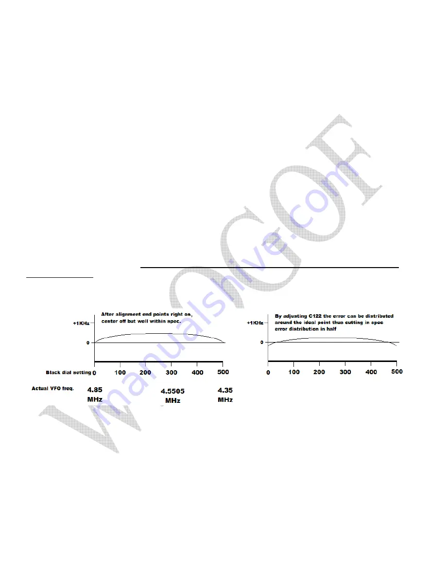
Rerun and record the data. If any of the mid points fall more than 2 KHz from spec knifing of C32A is indicated
(I use 1 KHz for my shop spec).
Knifing should never be attempted on the SR-400 unless you are very
skilled at knifing.
C120 is fragile and can be destroyed very easily. If you have a uniform distribution of the
error you can split the difference by adjusting C122. That is move the end points half the max error in the
opposite direction of the error.
This completes the oscillator test and adjustment process. Again let me stress that diligence in getting the
oscillators correct will pay max benefits in the end product.

