background image

Summary of Contents for SX-130

Page 1: ...OP therafiers OPERATING AND SERVICE INSTRUCTIONS COMMUNICATIONS RECEIVER MODEL SX 130...

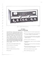
Page 2: ...being readily selectable by means of a front panel control This feature greatly simplifies tuning of single sideband signals Other features of the Model SX 130 include Product detector for CW and SSB...

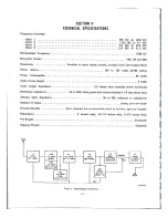
Page 3: ...wiscocs seen ois asMe REM ASE RES SS ERR REO oer 48 watts Adio Power Ouipul sa am sa eis ee eee BS eR Sita o aed wun dobme lbw wlan 2 watts Audio Output Impedance 0200 3 2 ohms rear mounted screw term...

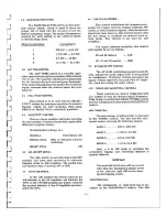
Page 4: ...a limited frequency range Generally speaking the same rules that apply to transmitting antennas will hold true for receiving antennas If an unbalanced or a single wire antenna is used connect one end...

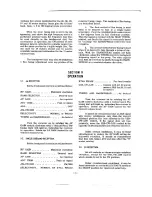
Page 5: ...r to the AF amplifier and disables the BFO In the CW SSB position the switch connects the product detector to the AF amplifier and ener gizes the BFO 4 8 USB CW LSB CONTROL This control establishes th...

Page 6: ...rols as outlined below meters USB for 20 15 and 10 meters RF GAIN Maximum clockwise TUNING AND BANDSPREAD As desired BAND SELECTOR Desired band AP GRIN my egies Ses ci rctieeseces As required Turn the...

Page 7: ...e screws have been removed slide the chassis forward and out of cabinet 6 2 TUBE AND DIAL LAMP REPLACEMENT Tubes may be replaced from the rear of the cabinet without removing the chassis When re placi...

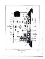
Page 8: ...METER ZERO v7 6Gwe Figure 6 Top View of Receiver age 196 006124...

Page 9: ...e performed only by persons familiar with communications receivers and ex perienced in their alignment 7 1 EQUIPMENT REQUIRED 1 Signal Generator covering 455 KC to 30 MC 2 Vacuum Tube Voltmeter VTVM 3...

Page 10: ...e as step 1 Same as step 1 Same as step 1 Same as step 1 Same as step 1 Same as step 1 SIGNAL 1400 KC RECEIVER CONTROL SETTINGS BAND SELECTOR 1 TUNING 1400 KC BAND SELECTOR 1 TUNING 600 KC BAND SELECT...

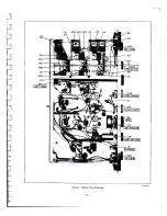
Page 11: ...C22 LIO C23 Cl A ae BAND siB j SELECTOR L5 ee i te D c Exo Lg J e Ff aS ci3 2 lan af tor ry ANT TRIM Five yw wf ce P C35 J iach Yl AVS J R45 AF GAIN Figure 7 Bottom View of Receiver warfilioas...

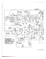
Page 12: ...D 3 BAND SELECTOR SWITCH SI SHOWN IN BANDI POSITION EXTREME COUNTERCLOCKWISE 4 SELECTIVITY SWITCH S4 SHOWN IN NORMAL LE POSITION 5 SWITCH S2 SHOWN IN ANL OFF POSITION SWITCH 3 SHOWN IN AM POSITION BAN...

Page 13: ...V6 6BE6 C45 BFO PRODUCT 0 005 DETECTOR v7 6GW8 AF AF AMPL OUTPUT 192v AM DET NOISE LIM R54 32m be on SPRR ae STD BY Be a GND 2 105 125 VAC 50 60 1 5 0003373 Diagram of Modes X 130...

Reviews: