background image

Confidential


66 


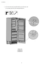
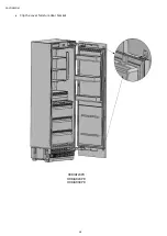
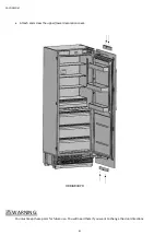
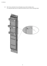
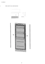
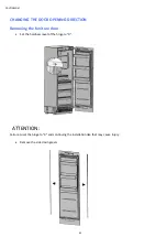
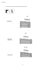
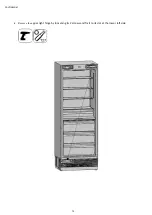
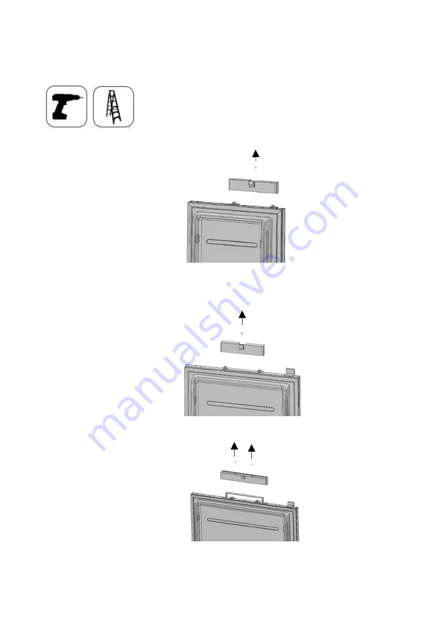
Loosen screws of the Upper Cover of the door and remove it. 


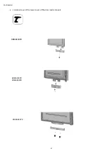
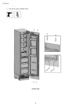
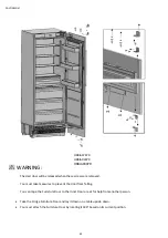
HRBIAR30PR


HRBIAF18PR


HRBIAF24PR 
HRBIAR24PR 
 

Summary of Contents for HRBIAF18PR

Page 1: ...Confidential 1 Refrigerator Installation Manual All Freezer HRBIAF18PR HRBIAF24PR All Refrigerator HRBIAR24PR HRBIAR30PR...

Page 2: ...i tip method 29 Preparing the water hose and the power Plug 30 INSTALLATION TO THE CABIN 31 Taking the refrigerator from the wooden pallet 31 Placing the refrigerator into the cabin 32 Adjusting the h...

Page 3: ...djusting the hardness of the hinges 64 CHANGING THE DOOR OPENING DIRECTION 65 Removing the furniture door 65 Removing and preparing the Inner door 70 Replacing the hinges 72 Air vent upper part direct...

Page 4: ...osed safely and kept out of the reach of children Please return the packaging to your dealer WARNING This installation manual has been prepared to help installation teams The User Manual provided with...

Page 5: ...two terminal adapters must not beused ATTENTION You must wear gloves and eye protectors when installing the product You must also take measures against high noise levels when drilling the floor or us...

Page 6: ...Confidential 6 Load bearing capacity of the door bins Category HRBIAF18PR HRBIAF24PR HRBIAR24PR HRBIAR30PR Max load 22Ibs 10kg 33Ibs 15kg 33Ibs 15kg 55Ibs 20kg...

Page 7: ...ill be installed must be checked with a Bubble Level Tool Installation area must not be subjected to direct sunlight and it must be away from heat sources ovens radiators etc The ambient temperature m...

Page 8: ...UL list and ready to be connected to a 120 V 60 Hz power supply Fuse is 15 A The appliance must be connected to a 3 pin socket The plug must be installed only by a licensed electrician If the electri...

Page 9: ...e electric shocks Do not remove the round grounding terminal from theplug Do not use two pin groundingadapters Do not use extension cables to energize theproduct ATTENTION Do not connect the grounding...

Page 10: ...ls to be used when installing the product are as follows Cordless Drill Safety Goggles Wrench Hammer Ladder 2 4 Drill bit 8 0 Drill bit Box Cutter Safety Gloves Tape measure Star bit Wrench Flat Bubbl...

Page 11: ...d on the kitchen design It must be installed at a place where it is ensured that the door can be opened and closed properly If the doors cannot be opened 90 degrees at least you cannot completely open...

Page 12: ...ir own box is jammed between the two kitchen cabinets or decorative columns This is the most common installation scenario Cabin dimensions Cabin dimensions below must be checked before startingthe ins...

Page 13: ...hin the range given below ATTENTION Do not use extension cables or two pin adaptors and do not remove the ground terminal of the grounding cable ATTENTION A qualified electrician must ensure that the...

Page 14: ...water pressure exceeds 80 psi install a pressure limiting device or water impact protector to the inlet valve Never install the product or operate the appliance if it is possible for the water pressu...

Page 15: ...e the product will be installed must be checked with a Bubble LevelTool Uprightness of the furniture flanges must be checked with a Bubble Level tool If the flatness and uprightness of the product is...

Page 16: ...t dimensions Category HRBIAF18PR HRBIAF24PR HRBIAR24PR HRBIAR30PR A 17 3 4 451mm 23 3 4 603mm 23 3 4 603mm 29 3 4 756mm 79 15 16 2030mm 83 9 16 2123mm without panel 23 5 16 592mm with panel 24 616mm 3...

Page 17: ...earance to adjacent wall 90 reduced internal access C Minimum door clearance to adjacent wall 115 full internal access Category HRBIAF18PR HRBIAF24PR HRBIAR24PR HRBIAR30PR A 20 508 26 660 26 660 32 81...

Page 18: ...mm 1 16 2mm 1 8 3mm 84 2134mm 3 4 19mm Remaining space after install Minimum height adjustment for leveling Anti tip bracket location 5 32 4mm 84 2134mm 83 27 32 2130mm Front 5 16 8mm Rear 7mm 4 101mm...

Page 19: ...Height of the kitchen countertop based on the min max height of the cabin A B standard 4 101mm 84 2134mm minimum 3 3 4 96mm 83 13 16 2129mm maximum 5 3 8 136mm 85 3 8 2169mm Gap 1 8 3mm 3mm 4 101mm G...

Page 20: ...Confidential 20 Category HRBIAF18PR BRBIAF24PR HRBIAR24PR HRBIAR30PR C 18 457mm 24 609mm 24 609mm 30 762mm D 17 3 4 451mm 23 3 4 603mm 23 3 4 603mm 29 3 4 756mm...

Page 21: ...l 21 Unpacking WARNING At least two persons must carry the refrigerator Use a box cutter to remove the tapes Cut the Packaging Board with a Box Cutter through the section illustrated in dotted lines a...

Page 22: ...Confidential 22 Remove the Packaging Polystyrenematerial ATTENTION Do not remove the tape of the upper door on the product until the refrigerator is placed into the cabin Risk of tipping over...

Page 23: ...4 30 1 Trim furniture top PVC extrusion L 457 1 PVC extrusion L 609 1 PVC extrusion L 762 1 2 Trim furniture side PVC extrusion L 1 259 2 2 2 PVC extrusion L 617 2 2 2 3 Trim door side PVC extrusion L...

Page 24: ...T1 0 Cr zn coating 4 4 4 10 Center mounting bracket T1 0 Cr zn coating 4 4 4 11 Counter sunk head screw ST4x14 8 8 8 12 Bracket furniture T1 0 Cr zn coating 8 8 8 13 Counter sunk head screw ST M4x14...

Page 25: ...25 Removing the vent hole assembly Remove 5 screws to take out the Vent Hole Assembly...

Page 26: ...ng the anti tip brackets WARNING You must definitely use Anti Tip Brackets to prevent the appliance from tipping over WARNING Make sure that there is no electrical or water connection where the screws...

Page 27: ...Confidential 27 Use a drill to create holes for dowels item No 2 at the marked points 5 16 8 Use the hammer to fit the dowels item No 2...

Page 28: ...connection parts are fit to the wall as securely as they should be you can use alternative anti tip methods If there is furniture at the back wall of the refrigerator please make sure that the furnitu...

Page 29: ...m section dimensions of the wooden girder must be 3 x4 75 mm x 100 mm Width of the girder must be equal to the clearance where it will be installed An additional girder must be used if the niche depth...

Page 30: ...has a thread with an external diameter of must be used to connect the hose end to the product You can choose the method A or method B below to prevent the cable from gettting jammed Method A Locate th...

Page 31: ...emove the brackets that connect the refrigerator to the WoodenPallet Recline the refrigerator slowly and pull back with the help of the cart and then landit ATTENTION The risk of tipping over is high...

Page 32: ...Confidential 32 Placing the refrigerator into the cabin Insert the mains water hose into the duct at the back and take it out from thefront...

Page 33: ...en placing the product WARNING The plug of the product must be accessible after installation If the plug is not accessible after installation the power must be cut off from the main switch WARNING Mak...

Page 34: ...dential 34 IMPORTANT INFORMATION You must use the upper edges of the door when aligning the product with the furniture Adjustment of other edges are explained in the following pages 4 101mm 1 8 3mm 1...

Page 35: ...et to reduce the risk of the cabin falling frontward A D Turn the key clockwise to lift the front B C Turn the key clockwise to lift the rear After adjusting the adjustable feet check the flatness in...

Page 36: ...usting the refrigerator according to the cabin flange For product with furniture door the position of the Refrigerator is adjusted so that the door and the furniture surface are flush You can also use...

Page 37: ...re door the product is placed using the adjustment part as shown in the figure below Position of the level adjustment part 10 must be adjusted according to the thickness of the door It can adjust the...

Page 38: ...urnitures Item No12 to the unit where 2 on the top and 3 on every side Use the truss washer head screws Item No14 to tighten WARNING Before starting to screw the Side and Upper brackets please make su...

Page 39: ...acket furniture on the cabin side wall Attach the bracket furniture to the furniture with 12screws ItemNo13 z IMPORTANT INFORMATION If you have difficulty tightening the screws opening a reference hol...

Page 40: ...the hose coming fromthe valve WARNING The hose coming from the mains must be one piece Do not use extension hoses WARNING Make sure that the power is cut off when making the water connection of the pr...

Page 41: ...WARNING Pressure of the water system must be between 25 80 psi 1 7 5 5 Bar IMPORTANT INFORMATION Once the connection is complete you must turn on the mains valve and make sure that there is no leakag...

Page 42: ...ANT INFORMATION You can move the lower vent hole forward backward to adjust it to the kick plate in the kitchen WARNING Forward backward travel distance of the lower kick plate must be 15 16 23 mm As...

Page 43: ...ttaching the decorative parts Attach the side closing parts trim furniture side ItemNo2 onto the right left connectionbrackets Attach the upper closing part trim furniture top ItemNo1 onto the upper c...

Page 44: ...HRBIAF18PR HRBIAF24PR HRBIAR24PR HRBIAR30PR Weight 66 0 lbs 30 kg 66 0 lbs 30 kg 66 0 lbs 30 kg 66 0 lbs 30 kg Furniture door density 0 6 Choosing the door thickness The door of your refrigerator can...

Page 45: ...of your door to 90 If you want 90 limit pin item No 17 is located in the mouting part kit of the drawer box Pin must be fully seated in the bracket or the door will not close properly 90 limit pin sh...

Page 46: ...o take out the top hanger bracket cover WARNING There is a magnet on the top hanger bracket cover This is a functional part for the operation of the product It should not be confused with the low hang...

Page 47: ...Confidential 47 Remove screw to take out the low hanger bracket cover HRBIAF18PR HRBIAF24PR HRBIAR24PR HRBIAR30PR...

Page 48: ...Confidential 48 Removing the panel adjustment mechanisms on the refrigerator Remove the upper and lower adjusting mechanism assemblies from the door HRBIAF18PR...

Page 49: ...Confidential 49 HRBIAF24PR HRBIAR24PR HRBIAR30PR TF 18BINFIA...

Page 50: ...cradle parts on the furniture door When marking you can use the Furniture door preparation template provided with the product WARNING Handle connection holes must be adjusted according to the handles...

Page 51: ...15 16 23 3 4 79 15 16 23 3 4 79 15 16 29 3 4 29 15 16 1 2 12mm 3 1 2 89 7mm 79 15 16 2030mm 26 7 8 683 5mm 6 1 2 165 5mm 23 7 8 606 5mm 7 10 18 2mm 1 2 12mm HRBIAF18PR HRBIAF24PR HRBIAR24PR HRBIAR30PR...

Page 52: ...uitable for the door thickness Install cradles using the chipboard screws You can also use the template provided with the product to align these parts It is recommended to keep this template for futur...

Page 53: ...e must not protrude Attach the door handle to the furniture door Screws holding the door handle must not protrude WARNING Handle connection holes must be adjusted according to the handles to be used i...

Page 54: ...Confidential 54 Installing the furniture door 1 Attach the furniture door to the door...

Page 55: ...t 3D direction using by two fixing bolt to perform fine adjustments First of all review the position of the grouped Furniture Doors against the kitchen furniture Distances between furniture must be 1...

Page 56: ...Confidential 56 How to align the furniture door lower part with bolts Up down Left right Fixing furniture door completely Front back...

Page 57: ...Confidential 57 Use the bracket furniture door Item No6 to join the furniture door Use 2screws Item No7 and 1screw Item No5 to fix HRBIAF24PR HRBIAR24PR HRBIAR30PR...

Page 58: ...Confidential 58 Clip the cover furniture door bracket HRBIAF24PR HRBIAR24PR HRBIAR30PR...

Page 59: ...Confidential 59 Attach and screw the upper lower decorationcover HRBIAF18PR...

Page 60: ...Confidential 60 Attach and screw the upper lower decorationcover HRBIAF24PR HRBIAR24PR...

Page 61: ...Confidential 61 Attach and screw the upper lower decorationcover WARNING You must keep these parts for future use You will need them if you want to change the door directions HRBIAR30PR...

Page 62: ...Confidential 62 After the top and bottom door panel brackets are secured by installing screws use screw Item No8 and square washer Item No9 to secure the center mounting bracket...

Page 63: ...Confidential 63 Attach the Trim door side Item No3...

Page 64: ...drill to adjust the hardness of the upper and lower hinges of the Door Set the hingeadjustment screw from position O to position I WARNING The door must be fully open during this adjustment WARNING Th...

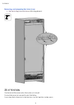
Page 65: ...THE DOOR OPENING DIRECTION Removing the funiture door Set the hardness level of the hinge to 0 ATTENTION Failure to set the hinge to 0 and continuing the installation like that may cause injury Remov...

Page 66: ...Confidential 66 Loosen screws of the Upper Cover of the door and remove it HRBIAR30PR HRBIAF18PR HRBIAF24PR HRBIAR24PR...

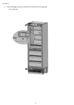
Page 67: ...Confidential 67 Loosen screws of the lower cover of the door and remove it HRBIAF24PR HRBIAR24PR HRBIAF18PR HRBIAR30PR...

Page 68: ...Confidential 68 Remove the upper adjustment kits HRBIAF18PR...

Page 69: ...to prevent the door from falling You can tape the Furniture Door to the Inner Door or ask for help from another person Take the Fridge Furniture Door and lay it down on a table upside down You must a...

Page 70: ...the hinge connection screws of the HingeBrackets ATTENTION The clad door will be released when these screws are removed You must take measures to prevent the door from falling You can tape the Furnitu...

Page 71: ...Confidential 71 Take out door and lay it down on a table Remove the hinge brackets on the fridge door and screw them as shown figure...

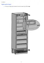
Page 72: ...Confidential 72 Replacing the hinges Remove the Hinge Caps located at the other side where you will fix thehinges...

Page 73: ...Confidential 73 Remove the lower right hinge by loosening its 2 screws and fix it to its slot at the upper left side...

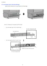
Page 74: ...nt part and change direction as shown figure Air vent cover Air vent hinge part right Rotate air vent cover by 180 rotate Air vent hinge part left Air vent upper part for the right hinge How to change...

Page 75: ...Confidential 75 Remove the upper right hinge by loosening its 2 screws and fix it to its slot at the lower left side...

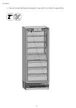
Page 76: ...Confidential 76 Attach the Hinge Slot Caps removed from the left side to the Hinge Caps to the rightside...

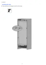
Page 77: ...Confidential 77 Installing the door Place the door to the refrigerator and fix it with 4screws...

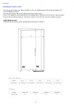
Page 78: ...seat into the gap and a material that can be their own box is jammed between the two kitchen cabinets or decorative columns This is the most common installation scenario Cabin Dimensions Cabin dimensi...

Page 79: ...two pin adaptors and do not remove the ground terminal of the grounding cable ATTENTION A qualified electrician must ensure that the poles of the socket are connected correctly Verify that the ground...

Page 80: ...ater impact protector to the inlet valve Never install the product or operate the appliance if it is possible for the water pressure to exceed 120 psi WARNING Make sure that there is no water leakage...

Page 81: ...ponge Sponge gray T3 0 400 1750 1 2 Connecting bracket T2 0 Cr zn coating 1 3 Truss washer head M4 12 16 4 Fastener POM 3 5 Trim furniture middle PVC extrusion L 1876 1 Truss washer head screw Spec M4...

Page 82: ...tial 82 Attaching the fasteners and connecting bracket Screw 3 the Fasteners 4 that are going to be used to connect two refrigerators together to the locations shown in the figure Connecting bracket F...

Page 83: ...Confidential 83 Stick the Insulation Sponge 1 to the side panel so that the sponge remains in between two cabins...

Page 84: ...Confidential 84 Bring the two refrigerators side by side After making sure that they are in alignment screw the fasteners 4 to the other refrigerator...

Page 85: ...Confidential 85 Make power and water connections of the refrigerator as explained before Push the refrigerators into the cabin...

Page 86: ...or in the cabin Adjust the refrigerator height using the adjustable feet WARNING First of all raise the front feet to reduce the risk of the cabin falling frontward A D Turn the key clockwise to lift...

Page 87: ...Confidential 87 Screwing the bracket furniture on the cabin side wall Attach the bracket furniture to the furniture with 12screws z...

Page 88: ...Confidential 88 Screwing the bracket furniture on the cabin top wall Attach the bracket furniture to the furniture with 4screws...

Page 89: ...Confidential 89 Attaching the decorative parts Attach the side closing parts onto the right left connectionbrackets Attach the upper closing part onto the upper connectionbracket...

Page 90: ...Confidential 90 Attach the middle closing parts trim furniture middle ItemNo5 between two refrigerators...

Page 91: ...Confidential 91 You can see previous pages for other installation procedures...

Page 92: ...Confidential 92...

Reviews: