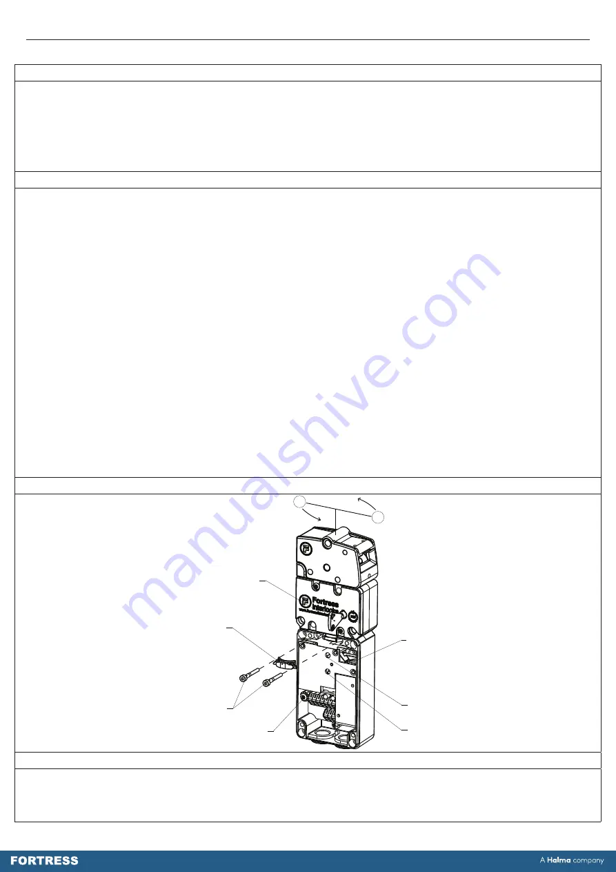
Operating Instructions: Single Action Escape Release Head & Handle
6
Tools and Fixings Required
Ø8.2mm Drill
Ø6.2mm Drill
3 x M8 screws
(Rear fixing)
3 x M8 Washers
3 x M6 Screws
3 x M6 Nuts
(Optional)
3 x M6 Washers
Mounting (Escape Release
Head)
1.
Locate the amGard
pro
unit containing the escape release head so it is in a suitable position for the accompanying
amGard
pro
stack and within reach for easy user operation.
2.
Remove the tongue assembly from the unit by removing the locking means (e.g. Solenoid, Key, etc.) and pulling the
tongue out of the head by means of the silver handle.
3.
Mount the enclosure assembly together with head assembly to a flat metal, static part of the machine. Use M8 screws from
the rear. The mounting surface should be flat.
4.
The head may be rotated in increments of 180° to suit the installation.
i.
Remove M5 pin hex screws from host (
pro
LOK /
pro
LOK+) lid.
ii.
Remove 2 x M4 screws retaining head and remove the M4 screws and clamp.
iii.
Turn to preferred orientation.
iv.
Replace clamp, 2 x M4 head fixing screws, lid and lid screws.
5.
Make sure that the gap around the perimeter of the guard, when closed (Safety Circuits Closed), does not exceed the limits
specified in the relevant standards.
6.
All fixing screws must be permanently prevented from removal,either by vibration or by personnel using standard tools.
7. Ensure each of the three M8 head fixings are used to guarantee correct operation and maximum head
retention force.
8.
The installation and operation of the complete guard interlocking device must take into account the requirements of EN
ISO 14119; in particular Section 7 – Design for minimising defeat possibilities.
9.
The complete guard interlocking device must not be used as a mechanical stop. Where applicable, precautions must be
made to ensure the door or gate of any guarded area has sufficient support and stops to prevent the impact on the guard
interlocking device.
10.
The complete guard interlocking device must be mounted in the correctly assembled condition so that the escape
release action is only possible from within the guarded area (danger zone).
Figure 6:
Mounting (Escape Release Handle)
1.
Mount the unit only in its correctly assembled condition: i.e. Ensure unit is assembled for the correct handing required for
the particular installation.
2.
Locate the handle so that it is within easy reach. Locate the interlock so that operation of the auxiliary unlocking
mechanism, and inspection and replacement of the interlock are possible.
www.fortressinterlocks.com
Fortress
Interlocks
NEW STLYE I6 HEAD CAN BE ROTATED WHILST STILL ATTACHED TO LOK
2
4
Escape Release
Reset Key for I6 & I7
Versions Only
M4 x 30 Cap
Head Screws
Solenoid
Plunger
Upper
Plunger Hole
Earth Point
Lower
Plunger Hole
Clamp


