background image


000-10000-190-02-

201511


5


Chapter 2   

HL-3 Specifications


This section provides information on the operating environment and specifications of the HL-3 Series 
light sources. 

Operating Environment 

The following table provides information on optimizing the operating environment of your HL-3. 

Operating Environment 

The HL-3 Unit . . . 

Moisture 

Is designed for operation in dry rooms only. 

Ventilation 

Should be placed so that its location or position does not interfere with proper 
ventilation. 

Heat 

Should be placed away from any device that emits excessive heat. 

Object and Liquid Entry 

Should be positioned so that objects do not fall on top of the unit. Additionally, 
ensure that no liquids are spilled into the enclosure through openings. 

Specifications 

Specification 

Value 

Spectral Range (calibrated): 
   Regular Models 
   Regular 

plus

 Models 

   EXT Models 

 
350 

– 1100 nm 

350 

– 1050 nm 

350 

– 2400 nm 

Dimensions (LWH): 
   HL-3-CAL and HL-3-CAL-EXT 
   HL-3-INT-CAL and HL-3-INT-CAL-EXT 
   HL-3 

plus

-CAL and HL-3 

plus

-CAL-EXT 

   HL-3 

plus

-INT-CAL and HL-3 

plus

-INT-CAL-EXT 

 
13.5 cm x 5.8 cm x 5.9 cm; 5.3" x 2.3" x 2.3" 
12.8 cm x 5.8 cm x 5.9 cm; 5.0" x 2.3" x 2.3" 
14.5 cm x 6.3 cm x 6.1 cm; 5.7" x 2.5" x 2.4" 
13.8 cm x 6.3 cm x 6.1 cm; 5.4" x 2.5" x 2.4" 

Power Input 

12 VDC/800 mA 

– 1100 mA (regulated) 

Bulb Life 

10,000 hours (recalibrate after 50 hours of use) 

Output to Bulb 

5 V / 1.0 A 

Time to Stabilized Output 

15 minutes 

Summary of Contents for Ocean Optics HL-3 plus -CAL-EXT

Page 1: ...ight Sources Installation and Operation Manual For Products HL 3 CAL HL 3 CAL EXT HL 3 INT CAL HL 3 INT CAL EXT HL 3 plus CAL HL 3 plus CAL EXT HL 3 plus CAL INT and HL 3 plus CAL INT EXT Document 000...

Page 2: ...from Ocean Optics Inc Trademarks All products and services herein are the trademarks service marks registered trademarks or registered service marks of their respective owners Limit of Liability Ever...

Page 3: ...ate an unsafe operating environment 2 Dangerous voltages are present in this device There are NO user serviceable parts inside 3 Only allow qualified personnel to service this unit 4 Inspect this unit...

Page 4: ...Important Safety Notices B 000 10000 190 02 201502...

Page 5: ...e HL 3 3 Connecting a Spectrometer to the HL 3 CAL Models When Using a Cosine Corrector 3 Connecting a Spectrometer to the HL 3 INT CAL Models When Using an Integrating Sphere4 Chapter 2 HL 3 Specific...

Page 6: ...Table of Contents ii 000 10000 190 02 201511...

Page 7: ...r 1 Setup Contains a list of package contents and unpacking instructions Also contains procedures for connecting to a spectrometer Chapter 2 HL 3 Specifications Contains operating environment specific...

Page 8: ...hanges you must first contact Customer Support and obtain a Return Merchandise Authorization RMA number Please contact an Ocean Optics Application Scientist for specific instructions when returning a...

Page 9: ...ths expressed in W cm nm and in a radiant flux in W nm for the INT models Since the spectral intensity of the HL 3 Series can be traced to an intensity standard traceable to the National Institute of...

Page 10: ...ncertainty to 3 and offer a shutter Model Calibrated Wavelength Range Maximum Uncertainty Level Shutter HL 3 plus CAL 350 1050 nm 3 Yes HL 3 plus CAL EXT 350 2400 nm 3 Yes HL 3 plus INT CAL 350 1050 n...

Page 11: ...when using a cosine corrector 1 Loosen the set screw on the HL 3 s SMA barrel and the CC 3 cosine corrector adapter slot 2 Screw the CC 3 cosine corrector onto the end of the fiber The connection sho...

Page 12: ...ug the wall mount AC adapter into a standard outlet 4 Turn the lamp on Allow the lamp to warm up for at least 15 minutes before using it 5 Insert the calibration disk that came with your light source...

Page 13: ...uld be positioned so that objects do not fall on top of the unit Additionally ensure that no liquids are spilled into the enclosure through openings Specifications Specification Value Spectral Range c...

Page 14: ...2 HL 3 Specifications 6 000 10000 190 02 201511 Specification Value Connector Regular Models INT Models CC 3 cosine corrector Integrating Sphere Shutter Regular Models plus Models No Yes...

Page 15: ...cedure Clear documentation of the calibration setup and of the calibrated devices used is an indispensable requirement Calibration for Absolute Irradiance Models HL 3 plus CAL HL 3 plus CAL EXT HL 3 C...

Page 16: ...S Stability S within 50 hours of operation 2 T and F Influence of temperature T and humidity F in the air The temperatures during calibration have a temperature range of 19 C to 25 C The humidity migh...

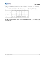
Page 17: ...ties and Uncertainty Budgets in at Wavelength Example 400 500 600 800 1000 1200 1600 1800 2000 2400 Standard uncertainty k 1 5 09 3 64 3 01 3 00 3 04 3 04 3 05 3 04 10 86 10 86 Expanded uncertainty k...

Page 18: ...A Calibration Basics 10 000 10000 190 02 201511...

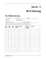
Page 19: ...ries Use Log Use Log No Page No ID No Lamp S N Date Calibrated Reference Standard Working Standard Note Do not exceed 50 hours of total ON time without recalibration Date Used Start Time Stop Time Pri...

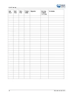
Page 20: ...B HL 3 Use Log 12 000 10000 190 02 201511 Date Used Start Time Stop Time Printed Initials Signature Running Total for on Time Comments...

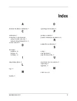
Page 21: ...ing sphere 4 cosine corrector 3 D document audience iii purpose iii summary iii I integrating sphere 4 L log 11 M models 2 O operating environment 5 P package contents 2 product related documentation...

Page 22: ...Index 14 000 10000 190 02 201511...

Reviews: