MAN1565-4
11
5.3
Earth Monitoring
The earth monitoring disable/enable feature is accessible via the SYSTEM menu at access level 3. Disabling the earth
monitoring does not illuminate the Earth Fault LED on the control panel.
Note:
If ZoneSense PLUS
is connected to a third party system which has earth monitoring and it’s earth
monitoring is being affected by
ZoneSense PLUS
even after being disabled through programming the resistor R22 on
the Main Card in
ZoneSense PLUS
can be removed.
5.4
Communications (TB2)
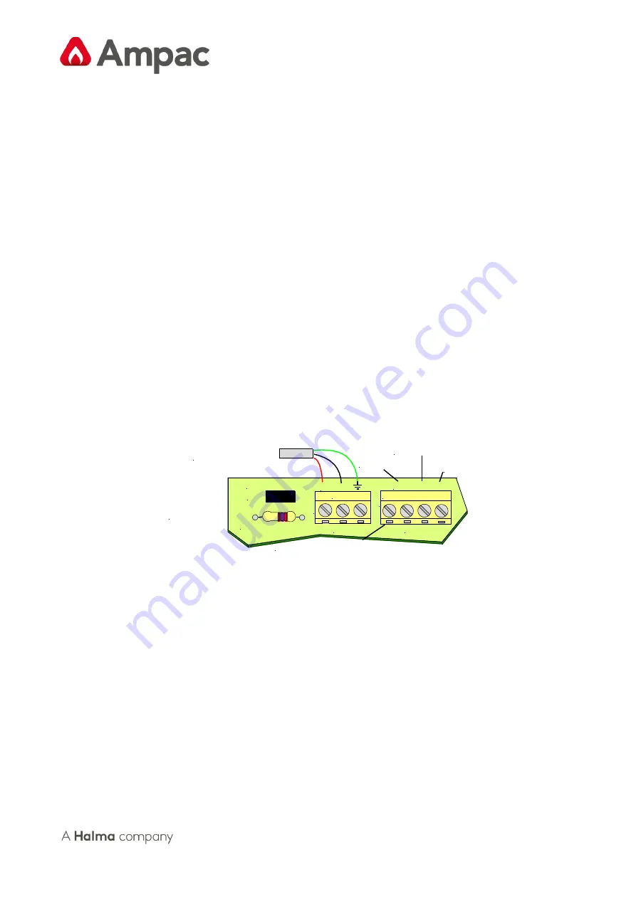
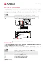
External Communications Terminals (RS485) TB2 1, 2 & 3
The RS 485 output drives the remote cards and mimics up to a distance of 1.2km from the FACP. The external cabling
(1 pair twisted shielded cable plus power) is wired to TB2 +, - and earth.
Note:
If a fault occurs on the communications line the common FAULT and SYSTEM FAULT LED’S will be
illuminated. Selecting the Faults Menu will display the fault details on the LCD.
5.4.1
Main Card Comms Link (K1)
K1 MUST be inserted when;
➢
Front door panel cards and the Main Card are used as an FACP; or
➢
Backpan boards and the Main Card are used as an FACP; or
➢
Remote boards and the Main Card are used as an FACP.
K1
C
o
m
m
s
+ -
Comms Link
TB2
Earth Disable
Top Left Hand
Corner of the
Main Card
To LAMs and/or
Remote Relay Boards
TB3
D/SW MCP FLT
Manual Call Point
Door Switch
Fault
In
p
u
ts
RS485
Com 1 2 3
Note: Terminate the 3 I/P's in 10K EOL
Figure 6: Comms Wiring Details


