MAN1565-4
35
1
2
3
4
ON
1
2
3
4
ON
1
2
3
4
ON
2
3
4
+27VDC OUT
TO NEXT LCS
+27VDC IN FROM
TERMINATION BRD.
10K
EOL
+
ON
Address
Switch
Set to 1
1
2
3
4
Agent Termination Board
within the FACP
Local Control Station
ONLY USED ON THE LAST
LCS ON THE COMMS BUS
10K
EOL
2K2
INTER
LOCK
INSERT A 2K2 ACROSS
THE 10K EOL TO
DEFAULT TO "ON"
TB4
T1
C N 1
LK2
TB2
TB1
S W 2
4
3
2
1
LK1
CN5
+
AGENT
MANUAL HOLD/
MANUAL
-
+
RS 485 OUT
RS 485 IN
-
+
RELEASE
0 V
+24V
C O M
LINK
TERMINATOR
C O M
0 V
+24V
BRD25ARB5-
INTER-
LOCK
-
JTAG
INHIBIT
SWITCH MON.
DISABLE
INHIBIT
EOL
S
IG
S
IG
S
C
R
N
27V 0 V
+
+
-
TB1
RS 485 COMMS BUS
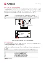
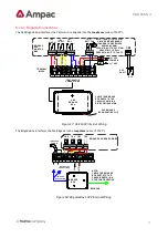
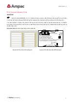
Figure 26: PCB Layout & Cabling Details
6.18
Agent Release Termination Board
SW1
+ LOCK-
+ L.PSW-
RELEASE
-
+
SIG+
SIG-
LCS CABLE
+ PSW -
INPUTS
N/0
STAGE2
GAS
+
-
N/0 C O M
N/0 C O M
+
SYST.
SCRN
+24VDC
+ -
0VDC
+ -
STAGE1
-
C O M
TB7
TB6
TB5
TB4
TB3
TB2
TB1
C
N
2
C
N
1
Address Setting
CN3
CN4
RS485 Control
Comms In
MAIN
RESV
+ - Outputs are Monitored
Fit EOL Termination
Link 1 to Last Module
on Comms Bus
1 2 3 4
O N
INOP
FIRED
MONITORED
Optional 27VDC In
RS485 Control
Comms Out
2
2K
2
2K
2
2K
1
0K
1
0K
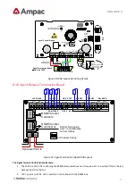
Figure 27: Agent Termination Board PCB Layout
The Agent Termination Board interfaces to;
1.
The FACP via CN1, CN2 continuing the RS485 communications bus if required. LK1 is inserted if this is the last
backpan board on the bus.
2.
LCS’s (up to 4) via TB1. LK1 is inserted in the last board in the RS485 Bus

