background image


4. Powering up.


[Back to contents]


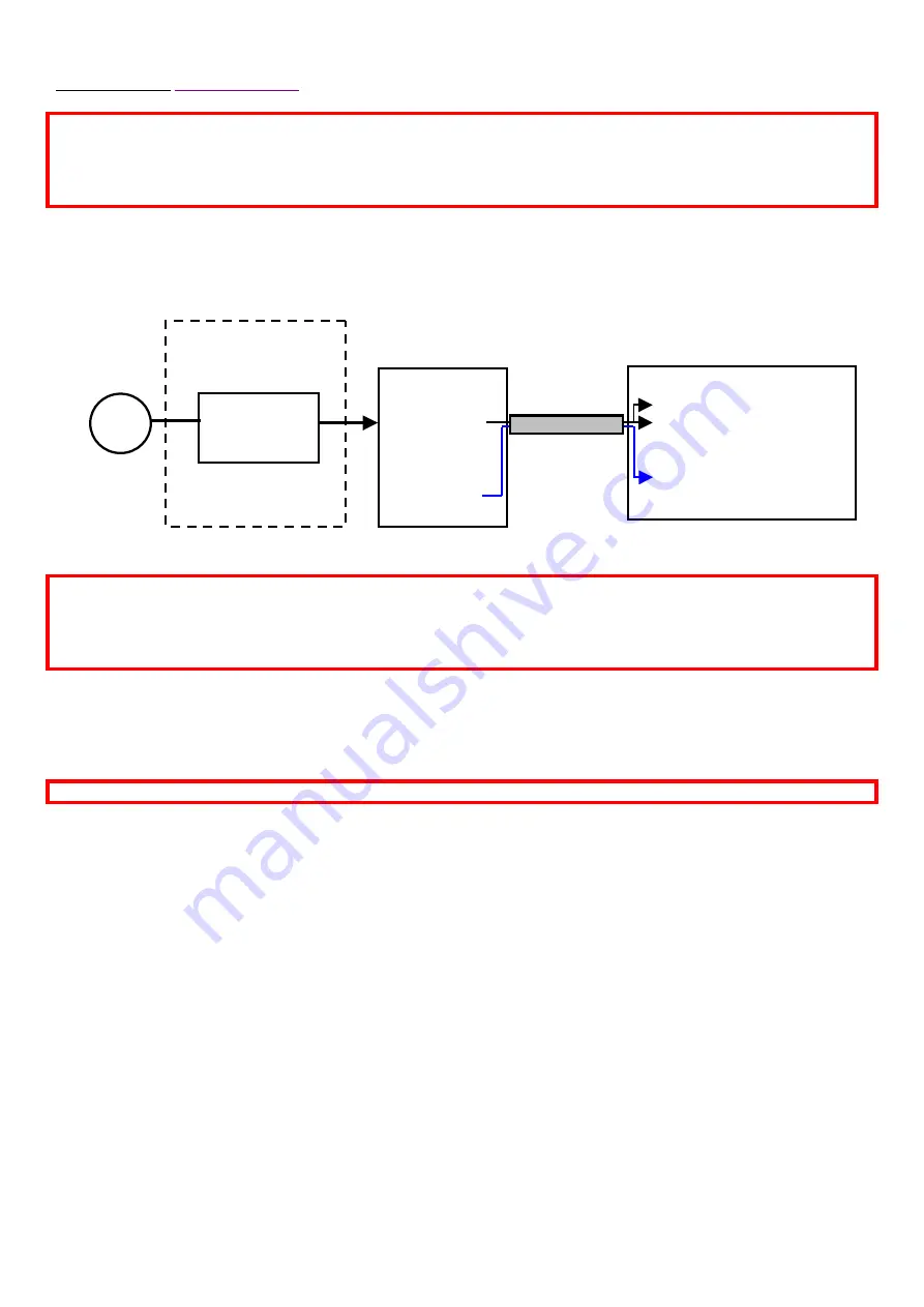
Connect the basic modules as shown in the schematic below. The order in which connections are made is not 
important. A time-delay device inside the LiDAR prevents ‘hot’ power from being applied directly to the internal sub-
components. 


**An additional fuse is fitted inside the UPS unit if the extended temperature range option is fitted. 


Once the UPS module has power, and is connected to the LiDAR, there may be a delay (of up to 20 seconds) before 
the LiDAR powers up. The thermal control system has power 10 seconds or so after power is applied to the LiDAR, 
and so the external fans may run. 

Note

 that if the fans are running, it doesn’t mean that the LiDAR is also powered, as 

they run from separate fuses and time delay units.  


When the LiDAR has power, the scanner will move to the home position and the internal PC will be fully booted 
approximately 1 minute later – indicated by the flashing green LED on the connector panel cluster. 


If the unit has been allowed to cool down to below 15ºC, then additional time will be needed before the unit 
can be run. Ideally, the system should be stored at room temperature (20ºC) for at least 24 hours prior to 
deployment. 


*

As indicated, a kit of parts can be supplied consisting of an enclosure, connectors and a suitable AC to DC PSU for 

use with the system. It will need to have the appropriate cable type and length sourced and the whole assembly wired 
by a qualified electrician. Halo can only supply mains rated components – they cannot be supplied in a wired state.  


It is advised that a 

keyboard, mouse and monitor be connected for the first power up

*

Optional kit of parts 

to be wired by a 
qualified electrician. 


LiDAR 

AC 

F1 (10A) LiDAR input 
F2 (10A) Passive & regular 
thermal control 
 

Extended TEC system 

600W  
AC / 24V DC 
power supply 

UPS module

 
24V DC input 
 
24V DC O/P 
 

**Internal 10A 
blade fuse 

UPS 
cable

Summary of Contents for Stream Line XR

Page 1: ...ntinuous and unattended mode of operation Typical applications include boundary layer wind profiling plume dispersion analysis of complex flows cloud studies cloud base measurements and gust and air q...

Page 2: ...irus is off Windows time syncing is disabled Daylight saving adjustment is disabled Video resolution is 1280 x 1024 BIOS settings The PC is set to come on with power The PC will come on at 12 20 PM if...

Page 3: ...to be observed at all times The LiDAR should be sited in such a way as to minimise the amount of heat generated by close surfaces such as tarmac or sunlight falling on it The temperature specification...

Page 4: ...nsit Case Packing and Unpacking 2 Connections 3 Power requirements and the UPS module 4 Powering up 5 Orientation and levelling 6 Site considerations 7 Routine cleaning 8 Typical thermal characteristi...

Page 5: ...he appropriate manual handling health and safety guidelines Unpacking reverse the process when packing The transit case consists of 3 separate pieces The LiDAR is packed fully assembled Remove the top...

Page 6: ...that it be left at this position The small pillars with rubber coned ends act as support legs when the 4 main legs are not attached They prevent the weight of the LiDAR being taken by the cooling agg...

Page 7: ...coming from the power supply module F 1 10A 5x20mm fuse for the LiDAR circuit F 2 10A 5x20mm fuse for the heaters and the thermo electric cooler TEC circuit if fitted There are 5 small LEDs close to...

Page 8: ...er un wired smaller connector and the white purging line The arrow on the power connector faces away from the LiDAR when it is the correct orientation The connector is a turn bayonet type Ensure that...

Page 9: ...e to the UPS and if a power cut happens a warning message will be displayed in the software tab area which will warn that a power cut is detected and the time remaining until the LiDAR shuts down With...

Page 10: ...e main connector body using a left hand thread Recommended PSU for connection to the 24V DC input power protection module It is recommended that the no load voltage of the PSU be turned up to 25 5V be...

Page 11: ...internal PC will be fully booted approximately 1 minute later indicated by the flashing green LED on the connector panel cluster If the unit has been allowed to cool down to below 15 C then additional...

Page 12: ...degrees Note For CSM scan files which are defined in motor encoder counts not degrees the offset bearing will not be used and all movements are with respect to the home position zero counts It will be...

Page 13: ...the heat generated underneath the LiDAR from direct sunlight a turfed area is ideal or shading if possible Ambient temperatures quoted in the temperature specification of the LiDAR are with respect to...

Page 14: ...coverage of the clear aperture is not too high The output window has a hard anti reflection coating on the outer surface The coating is reasonably robust but should it be deemed necessary to clean it...

Page 15: ...n If fuse F 2 is not blown then there may be a fault with the cooling unit in which case the LiDAR should be powered down to avoid the risk of it over heating Passive temperature option The heat excha...

Page 16: ...passwords needed to access the system are either removed or are sent to Halo prior to sending the system The system is packed in the same way that it was received The Unpacking section can be used for...

Reviews: