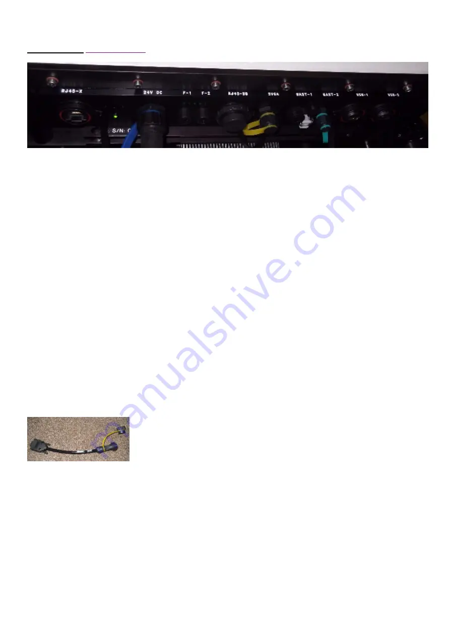
2. Connections.
From left to right:
RJ45-X
– This is for use with an RJ45 crossover cable, which will directly connect the internal PC to another PC.
Power
LED
and recessed internal
PC power
button.
The button will act in exactly the same way as a regular desktop PC power button. If the shutdown software has been
run and the PC is switched off, but the system is still powered, then a short press (duration of ½ second) will switch
the PC back on. It is not a reset button.
The power LED will light green when 24V DC is connected to the system. It doesn’t mean that the LiDAR components
are powered. There will be a power-up time delay after power is applied. If the fuse (F-1) has blown, the LED will not
be lit. If the time delay is still in progress, the LED will still be lit. When the left most LED close to F-1 and F-2 starts to
flash, it means that the PC is on.
24V DC
– this is the 24V DC power inlet coming from the power supply module.
F-1
– 10A 5x20mm fuse for the LiDAR circuit.
F-2
– 10A 5x20mm fuse for the heaters and the thermo-electric cooler (TEC) circuit if fitted.
There are 5 small
LEDs
close to the 2 fuse holders. 1 of them flashes once the internal PC is on and connected to the
control module. This LED is useful when diagnosing the PC’s status.
RJ 45-BB
– this is a standard RJ45 connection that can be connected to a regular hub or switch – used to connect the
LiDAR to the Internet or a LAN for use with the remote access software.
SVGA
– a circular connector requiring the supplied adapter cable to allow connection with a standard SVGA
connector.
Note that the internal PC video resolution is set to be 1280 x 1024 pixels, so the attached monitor will need to be
capable of supporting this resolution.
Mast 1
– Not used
Mast 2
– If the optional GPS module is fitted, then a connector as shown will be fitted; otherwise, the Mast-2
connector will be the same as the Mast-1 connector.
USB-1
and
USB-2
are both standard USB 2 connections to the internal PC. They can be used for connecting a
keyboard and mouse.


