97716C (Rev. A - 5/02)
HRFG - ER*A HRFG - SR*A HRFG - SER*A
INSTALLATION INSTRUCTIONS
1.
Install remote chiller
. Remove front panel of chiller. Remove and discard cardboard inner pack from be
tween compressor and side panel. Slide chiller onto the shelf and position it to the left within the guides
on the shelf.
NOTE:
Building construction must allow for adequate air flow on both sides, top, and back of chiller. A
minimum of 4" (102mm) on both sides and top is required. See chiller instructions for additional instructions.
2. Make water supply connections.
Attach an unplated copper water inlet line and a service stop (not
provided) to the chiller. Inlet port is marked on the chiller (3/8" O.D. copper tube). Bend the copper tube
(provided) at an appropriate length from chiller to opening in frame. Install a 3/8" O.D. tube tee fitting (pro
vided) on the marked chiller outlet port. Turn on the water supply and flush the line thoroughly.
3. Hang the upper panel on the mounting frame hanger
. Align holes in the panel with the holes in the
mounting frame. Be sure that panel is engaged with hanger at top of frame before releasing it.
4. Install fountain.
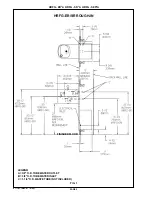
Remove access cover plate on underside of fountains and save the screws. Mount the
fountains to the upper panel and the wall frame with (4) 5/16" x 1-1/4" (32mm) long bolts, washers, and nuts.
Tighten securely, but do not overtighten. Over tightening will crack the Marblyte Fountain.
NOTE:
The short fountain should be mounted to the upper left hand side of the panel.
5. Remove elbow from end of p-trap and attach it to drain tube.
Re-attach elbow to p-trap and cut waste
tube to required length using plumbing hardware and trap as a guide.
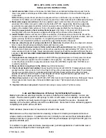
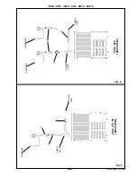
6. Make connection between remote chiller outlet tube and fountain strainer.
Insert the water inlet line
into inlet side of strainer by pushing it in until it reaches a positive stop, approximately 3/4" (19mm). Turn on
water supply and check for leaks. Newly installed water supply line should be insulated after leak check is
completed.
DO NOT SOLDER TUBES INSERTED INTO THE STRAINER AS DAMAGE TO THE O-RINGS
MAY RESULT.
7. These products are designed
to operate
on 20-105 PSIG supply line pressure. If inlet pressure is above
105 PSIG, a pressure regulator must be installed in the supply line. Any damage caused by reason of
connecting these products to supply line pressures lower than 20 PSIG or higher than 105 PSIG is not
covered by warranty.
8. Make electrical connections to the chiller.
See chiller instructions.
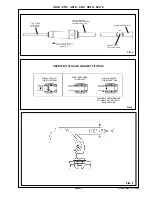
9. Check stream height from bubbler.
Stream height is factory set at 45-50 PSI. If supply pressure varies
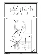
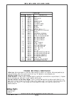
greatly from this, remove items 5 & 13 (See Figure 6, Page 6) by loosening set screw (item 10) and adjust
the screw on regulator (item 9). Clockwise adjustment will raise stream height and counter-clockwise
adjustment will lower stream height. For best adjustment stream height should be approximately 1-1/2"
(38mm) above the bubbler guard (See Figure 5, Page 5).
10. Mount lower panel.
Loosen the (2) #10-24 x 5/8" (16mm) screws at frame bottom lip. Slide upper tongue
of lower panel under lower edge of already installed upper panel. Tighten previously loosened screws
securely.
11. Replace bottom access panel
to fountain basin using screws provided. Tighten securely.
Care and Maintenance of Halsey Taylor Marblyte Fountains
Marblyte provides an exremely durable, nonporous surface which resists staining. Care is very
simple. Routine cleaning with a soft sponge or cloth, or with water or non-abrasive aerosol foam
cleaner, is all that is normally needed to give many years of trouble free service. Cleaners left
standing on the fountain surface can dull the surface finish. Be certain to rinse all cleaning agents
completely and polish with a soft cloth.
Harsh abrasive cleaners are not required and should not be used.
Mild abrasives such as liquid automotive cleaning compound or baking soda paste will remove
simple scratches and stains. Cigarette burns can normally be removed without noticeable effect.
Deeper scratches or gouges can be corrected with fine grit sandpaper (240 grit then 400 grit) or a
green Scotchbrite pad.
To maintain or regain luster and make cleaning easier, periodic applications of automobile wax or
like products will keep the finish looking like new.
PAGE 4

