background image

Page 5

98986C  (Rev. A - 5/12)

HTHBHVR*A   HTHBHVRBL*A   HTHBHVR8*1A   HTHBHVR8BL*1A

STANDARD TWO-LEVEL CONFIGURATION

STANDARD TWO-LEVEL REVERSED CONFIGURATION

1/4” HEX. HEAD BOLT THIS LOCATION ONLY

REMOVAL OF BOTTLE  FILLER FOR SERVICING

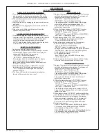
1)   Turn off the water supply to the Water Cooler(s). Unplug and/or turn off Circuit Braker to Cooler(s) and Bottle Filler. NOTE: the Lower Front Panel  

      of the cooler(s) may need to be removed. To prevent scratching the basin place a towel or soft cloth over the entire basin when working above it.

2)   

For Single Model Installations:

 Loosen but DO NOT remove the two (2) Pinned Torx Head Screws from the sides of the Bottle Filler. Remove the 

      two (2) Pinned Torx Head Screws from the Top Cover & remove the Top Cover.  The Bottle Filler may then be lifted up and off the Water Cooler 

      (The water line and Remote Reset Button Wires will still be connected from the Water Cooler to the Bottle Filler.). 

3) 

 For Two Level Model Installations: 

Loosen but DO NOT remove the Pinned Torx Head Screw from the outer side of the Bottle Filler and loosen but 

DO NOT remove the 1/4” hex. head bolt from between the two cooler (See Figs 6 or 7). Remove the two (2) Pinned Torx Head Screws from the Top 

Cover & remove the Top Cover.  The Bottle Filler may then be lifted up and off the Water Cooler (The water line and Remote Reset Button Wires will 

still be connected from the Water Cooler to the Bottle Filler.).

Fig. 6

Fig. 7

1/4” HEX. HEAD BOLT THIS LOCATION ONLY

Summary of Contents for HydroBoost HTHBHVR8

Page 1: ...CAL EQUIPMENT SUCH AS TELEPHONE COMPUTERS ETC TO WATER LINES IS A COMMON PROCEDURE THIS GROUNDING MAY BE IN THE BUILDING OR MAY OCCUR AWAY FROM THE BUILDING THIS GROUNDING CAN CAUSE ELECTRICAL FEEDBAC...

Page 2: ...1mm 48 1219mm O 5 16 8mm MOUNTING HOLES 3 PL 1 4 X 1 2 6mm X 13mm OBROUND HOLE 5 PL HANGER BRACKET 7 178mm 7 178mm 16 5 16 414mm 1 1 4 32mm 1 1 4 32mm Single Rough In Fig 1 HTHBHVR8 REDUCE HEIGHT BY 3...

Page 3: ...6 811mm RIM HEIGHT 8 203mm 18 1 16 459mm 7 178mm 7 178mm 1 1 4 32mm 1 1 4 32mm 16 5 16 414mm O 5 16 8mm HOLES 3 PL 5 3 4 146mm 5 3 4 146mm 1 3 8 35mm 1 3 8 35mm 18 1 2 470mm 3 1 2 89mm 4 1 2 114mm 6 1...

Page 4: ...ires from non refrigerated unit to the black wires on the refrigerated unit see step 4 7 For Single Model Installations Install remaining tube insulation to the water line from bottle filler connect B...

Page 5: ...ides of the Bottle Filler Remove the two 2 Pinned Torx Head Screws from the Top Cover remove the Top Cover The Bottle Filler may then be lifted up and off the Water Cooler The water line and Remote Re...

Page 6: ...n default back to bottle count and be back in run mode 2 When the display changes to SETTINGS depress the button again The display will change to show RNG SET Range set for IR sensor UNIT TYP Type of...

Page 7: ...See Fig 7 LISTA DE PIEZAS DEL FIL TRO Vea Fig 7 LISTE DES PI CES DU FIL TRE Voir Fig 7 PRINTED IN U S A FOR PARTS CONTACT YOUR LOCAL DISTRIBUTOR OR VISIT OUR WEBSITE WWW HALSEYTAYLOR COM PARA PIEZAS D...

Reviews: