Supplied By www.heating spares.co Tel. 0161 620 6677
20
7.1
OVERHEAT CUT OFF DEVICE
a)
Pull off the two electrical connections.
b)
Unscrew the overheat cut off device from the flow (upper)
manifold.
c)
Fit the replacement overheat cut off device, do not overtighten
connect the electrical wires (polarity is not important), and
re-assemble the appliance in reverse order.
7.2
FLOW TEMPERATURE THERMISTOR
a)
Pull off the two electrical connections.
b)
Unscrew the thermistor from the flow (upper) manifold.
c)
Fit the replacement overheat cut off device ensuring a small
amount of thermal paste is applied to the end of the
thermistor, do not overtighten connect the electrical wires
(polarity is not important), and re-assemble the appliance in
reverse order.
7.3
AIR PRESSURE SWITCH
a)
Pull off the three electrical connections, noting their positions
on the switch.
b)
Unscrew the two screws retaining the switch.
c)
Remove the switch, carefully pulling off the silicon tubes.
d)
Fit the replacement switch, connect the silicon tubes and
connect the electrical wires, ensuring they are in the correct
position. Re-assemble the appliance in reverse order.
7.4
IGNITION PCB
(FULLY ENCLOSED)
a)
Pull off the 12 way plug on the front of the ignition device.
b)
Unscrew the single screw which retains the ignition box.
c)
Remove the box by pulling it forwards, the ignition and
detection leads should be pulled off the box at this stage.
d)
Fit a new ignition device. Re-assemble the appliance in
reverse order.
7.5
AQUASTAT PCB & HOUSING
a)
Unclip the aquastat housing from its mounting plate on the
top of the gas valve by slightly pressing the two sides of the
housing inwards and lifting the housing upwards and
forwards.
b)
Carefully turn this housing over, pull off the electrical
connections.
c)
Remove the potentiometer from the housing by undoing the
hexagonal nut.
d)
Fit a new Aquastat & housing. Re-assemble in reverse order.
PARTS REPLACEMENT
7
Before commencing any replacement operation, ISOLATE the
mains electrical supply, remove the front painted panel by sliding
up and then away from the boiler, remove the right hand portion
of the inner case by first pulling off the control knob, then
unscrewing the upper and lower right hand screws (Fig. 15) and
sliding the case away from the appliance. TURN OFF the gas
supply at the main service cock.
After any replacement operation, commission the boiler as follows:
a)
Turn on gas and check for gas soundness around boiler
components using leak detection fluid. DO NOT USE A
NAKED FLAME.
b)
Remove the outlet pressure test screw and fit pressure test
gauge (see Fig. 29).
c)
Ensure that all secondary controls (timer, room thermostat and
cylinder thermostat where fitted) are turned to maximum.
d)
Turn on the electrical supply and check the pump is working
and is circulating water through the system.
e)
Turn the boiler thermostat fully clockwise to its maximum
setting. After a few seconds the boiler will light. The burner
flame can be viewed through the viewing glass in the front of
the sealed door.
f)
If the boiler fails to light, and the ignition reset neon
illuminates, wait 15 seconds and reset the ignition by
depressing the reset button once.
g)
Allow the boiler to operate for 10 minutes
h)
The gas rate can now be set as required by adjusting the
governor on the gas valve. See Figure 29. Turn clockwise to
increase the flow. For heat output/pressure setting refer to
table 2.1.
i)
Turn off the boiler and remove the pressure test gauge and
refit the pressure test screw. Check for gas soundness with
leak detection fluid.
j)
Refit the painted right hand inner case with the two screws,
then refit the control knob.
k)
Make sure all secondary controls (e.g. timer, thermostat, etc.)
do control the boiler correctly.
l)
Turn the boiler thermostat and all external controls to the
required setting and refit the front panel.
30
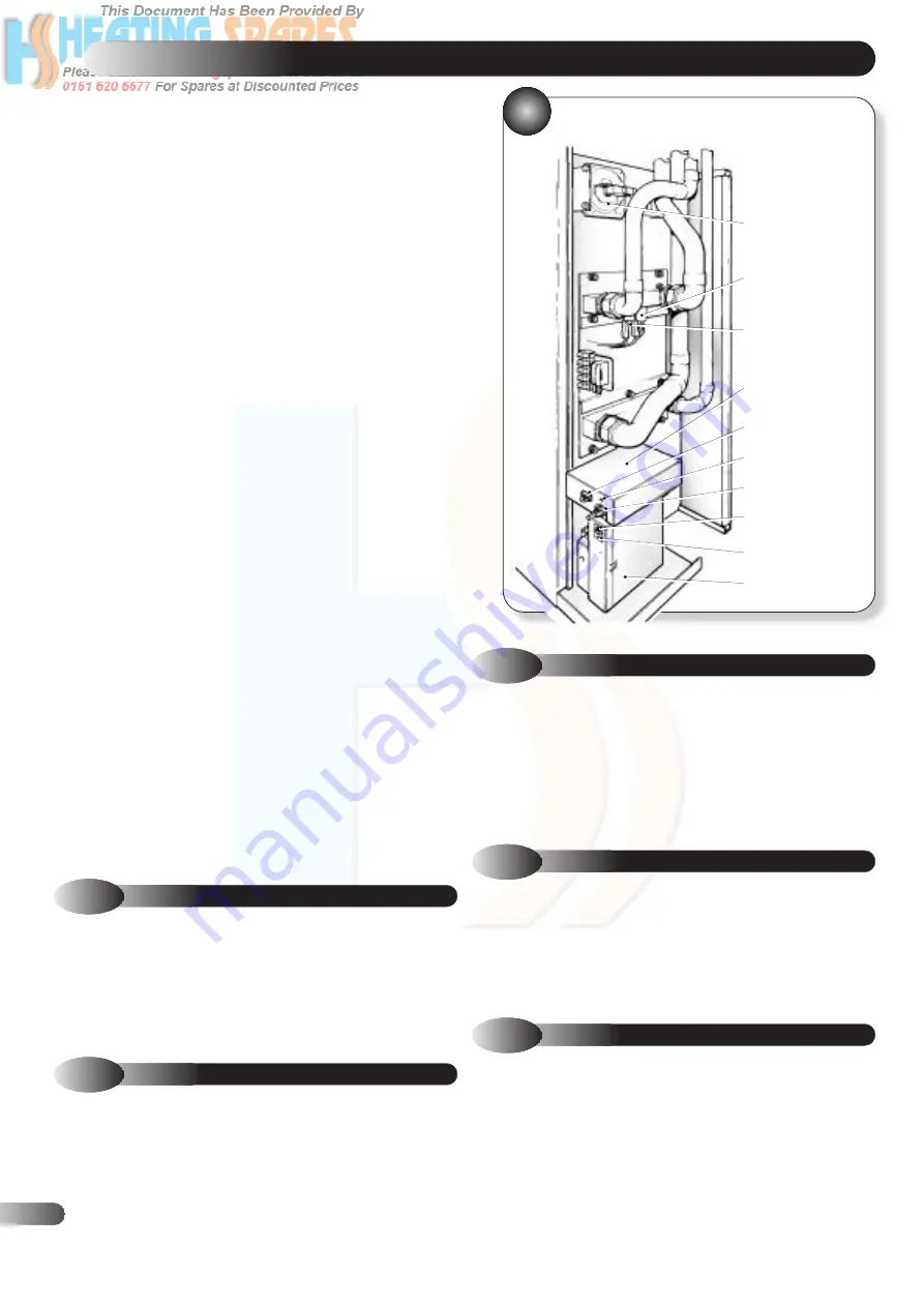
LOCATION OF SERVICEABLE
COMPONENTS
AIR PRESSURE
SWITCH
FLOW TEMPERATURE
THERMISTER
OVER HEAT
CUT OFF DEVICE
AQUASTAT PCB
(FULLY ENCLOSED)
JUMPER PLUG
OVERHEAT LOCKOUT
INDICATOR
TEMPERATURE CONTROL
POTENTIOMETER
IGNITION RESET
BUTTON
IGNITION LOCKOUT
INDICATOR
IGNITION DEVICE
(FULLY ENCLOSED)


