Supplied By www.heating spares.co Tel. 0161 620 6677
21
7.6
POTENTIOMETER
a)
Unclip the aquastat housing from its mounting plate on the top
of the gas valve by slightly pressing the two sides of the housing
inwards and lifting the housing upwards and forwards.
b)
Carefully turn the housing over. Note position of blue
insulation paper.
c)
Remove the potentiometer from the housing by undoing the
hexagonal nut and removing the two electrical connections
from the Aquastat.
d)
Fit a new potentiometer. Re-assemble in reverse order.
Ensuring that the blue insulation paper is correctly located.
METHOD 2
a)
Remove the four screws securing the left hand inner case.
Remove the case by sliding it forwards and off the appliance.
b)
Remove the combustion chamber front panel by pulling it
forwards out of the appliance.
c)
Dislocate the grommet from the boiler case.
d)
Slide the burner forwards out of the appliance taking care not
to strain the ignition and sensing electrode leads.
e)
Remove the ignition and sensing electrodes from the end of
the burner and set the burner aside.
f)
Unscrew and remove the injector and its sealing washer.
g)
Fit a new injector using a new sealing washer. Re-assemble
the appliance in reverse order.
7.8
GAS VALVE
a)
Unscrew the 4 screws which retain the gas service cock to the
gas valve.
b)
Unscrew the single screw which retains the ignition box to the
gas valve.
c)
Remove the box by pulling it forwards,the wires may remain
connected to the ignition device.
d)
Unclip the aquastat housing from its mounting plate on the
top of the gas valve by slightly pressing the two sides of the
housing inwards and lifting the housing upwards and
forwards.
e)
Unscrew and remove the aquastat housing bracket from the
top of the gas valve (4 screws). This may not be necessary if
the bracket is pre-fitted to the new gas valve.
f)
Unscrew the 4 screws which retain the manifold to the boiler
side.
g)
Remove the valve/manifold assembly from the boiler.
7.9
MAIN BURNER
a)
Remove the four screws securing the left hand inner case.
Remove the case by sliding it forwards and off the appliance.
b)
Remove the combustion chamber front panel by pulling it
forwards out of the appliance.
c)
Dislocate the grommet from the boiler case.
d)
Slide the burner forwards out of the appliance taking care not
to strain the ignition and sensing electrode leads.
e)
Remove the ignition and sensing electrodes from the end of
the burner and remove the burner.
f)
Fit the ignition and sensing electrodes to the new burner and
slide the new burner into position.
g)
Reassemble the appliance in reverse order.
31
ELECTRODE ALIGNMENT
a)
Remove the ignition electrode from the burner as described in
Section 7.9.
b)
Remove the aquastat housing as described in Section 7.5a.
c)
Pull the ignition lead off the ignition device on the gas valve
and completely remove the ignition electrode assembly.
d)
Fit a new ignition electrode and reassemble the appliance in
reverse order.
a)
Unscrew the two upper screws which retain the manifold to
the boiler side.
b)
Unscrew the two lower screws which retain the manifold to the
boiler side.
c)
Remove the whole assembly just enough to gain access to the
injector and unscrew the injector.
d)
Fit a new injector using a new sealing washer. Re-assemble
the appliance in reverse order.
7.7
BURNER INJECTOR
METHOD 1
h)
Separate the valve and manifold by unscrewing the
3 extended screws.
i)
Re-assemble in reverse order, ensuring all seals are in good
condition (replace where necessary).
7.10
IGNITION ELECTRODE
Front L/H of Burner
7.11
FLAME SENSING ELECTRODE
Rear L/H of Burner
a)
Remove the flame sensing electrode from the burner as
described in Section 7.9.
b)
Remove the aquastat housing as described in Section 7.5a.
c)
Pull the flame sensing lead off the ignition device on the gas
valve and completely remove the flame sensing electrode
assembly.
d)
Fit a new flame sensing electrode and reassemble the
appliance in reverse order.
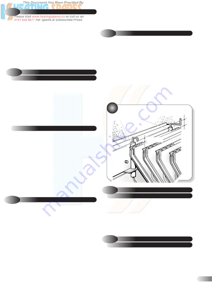
FLAME DETECTION
ELECTRODE
IGNITION
ELECTRODE
GAP
8mm to 10mm
SPARK GAP
2.5mm to 3.5mm


