Supplied By www.heating spares.co Tel. 0161 620 6677
23
23
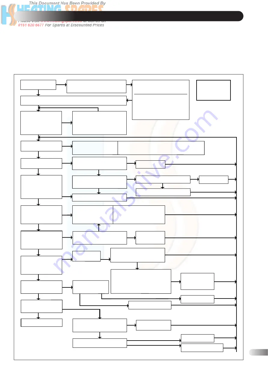
FAULT FINDING
9
Before proceeding through this fault finding guide, ensure all
connections to the electronic circuit board and the 12 way
connector to the ignition device are correctly fitted.
Carry out preliminary electrical safety checks in accordance with
‘Regulations for Electrical Installations’.
a)
Position the temperature control to 0.
b)
Turn ON external gas and electricity supplies.
c)
Ensure there is 230V at the permanent live ‘L’ on the
installation terminal block.
d)
Ensure there is 230V at the switched live ‘1’ on the installation
terminal block. This is the feed from the external controls,
they should be set to ON or MAXIMUM. A link between
terminals ‘L’ and ‘1’ will simulate the external controls
being ON.
Is the overheat
LED illuminated
Check 2Amp in-line fuse and replace if necessary.
If fuse continues to blow, check fan and pump for failure.
NO
YES
Switch off the permanent
supply to terminal "L" for 5
seconds minimum then back on.
The LED will now be out.
Investigate the cause of the
overheat situation and rectify.
Possible causes:
Lack of water
Lack of water flow
Faulty overheat thermostat
Faulty thermistor
Faulty aquastat
Turn the temperature
control knob to 6.
Is there 10vdc or 1vdc
at terminal 1 of the
igition control
connection
NOTE: The
Control System
incorporates an
Anti-cycle device
of 3 minutes.
The Thermistor, Potentiometer
or Aquastat PCB is faulty
re-place each in turn
separately to find and
rectify the fault.
1Vdc
Is the ignition Lock-out
neon illuminated.
Allow 15 seconds
minimum then depress
the ignition reset button
In the event of ignition lockout, turn thermostat
to maximum setting and ensure programmer
is switched on before pressing reset button.
YES
NO
Replace the fan
Is there 230V at the fan motor.
Replace the fan
YES
NO
Check the wiring and rectify.
Does the fan start
to run.
NO
NO
Disconnect fan leads from fan
motor. Is there between 40-50
ohms across fan motor.
YES
YES
Is there 230V at terminal
'8' on the ignition control
connection.
NO
Replace the ignition device.
Is there 230V at
terminal '7' on the
ignition control
connection.
YES
NO
Is there 230V at
terminal '5' on the
ignition control
connection.
YES
YES
Air pressure switch
has not changed over,
investigate and rectify.
Possible causes:
Air pressure switch faulty
Fan performance poor
Flue/Air duct blocked
Is there 230V at
terminal '6' on the
ignition control
connection.
NO
NO
Replace the
overheat
thermostat
YES
NO
Replace the
ignition device.
Does the gas valve open
and allow gas to the
main burner injector.
YES
Does the gas valve
open and allow gas
to the main burner
injector.
YES
NO
Is there a spark
between the ignitor
and the burner.
YES
Check the condition
of the electrode
and its lead.
NO
NO
Check the adjustment of the
gas valve. If this does not rectify
the fault replace the gas valve.
The original ignition device should
be used on the new valve.
It is unlikely both will be faulty.
Does the boiler ignite
and continue to
operate satisfactorily.
YES
Operation normal.
YES
SATISFACTORY
FAULTY
Replace ignition device.
Replace assembly.
Does the gas valve
open and allow
gas to the main
burner injector.
Is there 230V at terminal
N/O on the air pressure
switch.
YES
Does the burner ignite and
extinguish after approximately
10 seconds.
NO
Check the condition of the
flame sensor and its lead.
YES
Check the spark
gap and rectify.
Replace assembly.
Replace ignition device.
FAULTY
SATISFACTORY


