Supplied By www.heating spares.co Tel. 0161 620 6677
25
SUPPLEMENT 1
11
33
FLUE SYSTEM ASSEMBLY
AND DIMENSIONS
Supplementary instructions for flue systems with a vertical outlet.
a)
Read the installation requirements and flue specifications
described in section 3.
b)
Follow the installation procedure described in section 4 up to
section 4.7 (but making the necessary hole(s) in section 4.2 in
the ceiling/roof instead of the wall). Use the following
instructions in place of section 4.7.
c)
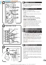
Measure the vertical distance from the top of the boiler case
to the roof line (Fig. 33). Use this length to calculate the
number of extension ducts required.
d)
Starting at the boiler, fit the vertical socket, standard duct and
extensions required. Then fit the adaptor.
e)
Now working from outside fit the Balanced flue roof terminal,
ensuring the roof flashing and sealing components are
secured to the roof.
f)
Ensure the inner and outer ducts are correctly fitted to the
adaptor.
Note: All the joints should be secured using the self-tapping screws supplied.
••
•
•
•
•
•
•
•
•
•
180mm
430mm
1046mm
max
30mm
767mm
767mm
767mm
425mm
50mm
See Figure 7 (page 6)
BALANCED FLUE
ROOF TERMINAL
•
ROOF LINE
•
100/60mm TO
118/80mm DIA
ADAPTOR
•
100/60mm DIA
EXTENSION DUCT
•
STANDARD DUCT
•
100/60mm DIA
EXTENSION DUCT
•
100/60mm DIA
EXTENSION DUCT
•
•
VERTICAL
SOCKET
•
SUPPLEMENT 2
12
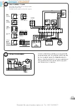
Supplementary instructions for flue systems incorporating
an additional 90° elbow.
a)
Read and follow the installation procedure described in the
main section of the installation instructions up to section 4.2.
b)
Using information given earlier in this booklet determine
where the boiler and flue are to be positioned and make the
necessary hole in the wall(s) for the air/flue duct as defined in
section 4.2.
c)
Install the boiler as described in section 4 with the exception
of the flue system (4.5)
d)
Using the information and dimensions in Figures 3 to 7 shown
earlier in this booklet calculate the lengths required for each
duct.
e)
Cut each duct to length, ensuring that each cut is square and
free from burrs.
f)
Starting at the terminal end assemble the ducts and elbows,
and work back towards the boiler.
IMPORTANT NOTE:
All flue joints must be secured by two self-tapping
screws through the air duct as illustrated.
For installations that require longer vertical or horizontal flue
lengths a twin pipe system is available. Refer to separate flue
booklet for further information.
34
These supplementary instructions must be read in conjunction with the
Installation and Servicing Instructions supplied with the appliance.
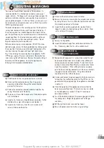
The entry of the concentric air/flue duct should be as close to the
centre of the entry face of the SE-DUCT as possible. It is very
important that the concentric air/flue duct is not positioned in the
corner of the SE-DUCT.
The standard flue kit supplied with the appliance is suitable for
installation in a SE-DUCT application. The appliance Installation
and Servicing Instructions should be used for the complete
installation with the exception of the following.
1 The external wall sealing ring should not be fitted.
2 The end of the air duct should be fitted flush with the inside of
the SE-DUCT as shown in the diagram below.
3 Horizontal flue installations only are suitable for SE-DUCT
applications.
SE-DUCT APPLICATIONS
CONCENTRIC AIR/FLUE
DUCT POSITION FOR
SE-DUCT APPLICATION
Seal the gap between the
SE-DUCT wall and the
100mm Dia.
appliance
air inlet
duct.
SE-DUCT
•
•


