23
2000225116B
IMPORTANT. On completion of the Fault Finding task which has required the breaking and remaking of the electrical connections,
the continuity, polarity, short circuit and resistance to earth checks must be repeated using a suitable multimeter.
WARNING. The multifunctional control and fan operate on mains voltage, the terminal will be live.
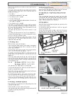
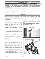
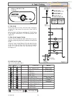
Diagram 9.1
ELECTRICAL FAULT FINDING
12062
9 Fault Finding
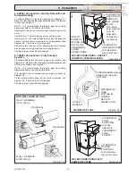
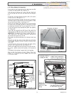
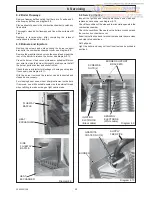
Diagram 8.12
ELECTRODE
0000
SECURING
SCREW
+
-
SPARK GAP
= 3.6 1.1
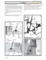
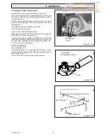
Diagram 8.11
BURNER
INJECTOR
GRAPHITE
COATED
NUT(2)
0939
8 Servicing
No
No
No
Before carrying out fault finding, ensure that gas, electricity and water are available to the boiler.
Ensure that any external controls are calling for heat and circuit water is cold.
If Reset LED is lit - check water system for overheating, reset by turning temperature control knob
off and on. If the LED coding is showing an ignition failure, reset the boiler by turning the control
knob off and on. Do not operate the boiler without combustion chamber front fitted.
Control Knob at '0'
Apply heating demand
(turn potentiometer clockwise)
Power ON at isolation switch
Does the fan run for 10 seconds with RESET LED lit
Replace fuse
Does the unit begin to spark
Replace PCB
Does the fan start
Is there an LED sequence
Turn Gas ON
Is there an LED sequence
Is the Gas turned ON
Replace PCB
Replace PCB
Correct Operation
Does the burner light
Refer to table
Refer to table
Switch OFF
Remake connections
Restart diagnosis
Are the HT & Earth
connections made
Yes
Yes
Yes
Yes
Yes
Yes
Yes
No
No
No
Refer to table
Yes
Yes
Yes
Yes
No
No
No

