18
221992D
6 Commissioning
IMPORTANT NOTE
The WARNING NOTICE attached to the front casing
must only
be removed by the user
Please ensure the “Benchmark” logbook is completed and left
with the user, and the magnetic lighting instruction label is
placed on the surface of the boiler casing.
6.1 All Systems
Commissioning should be carried out by a competent person in
accordance with the current issue of BS6798.
UNDER ALL CIRCUMTANCES the case must be correctly
fitted and sealed, unless fault finding.
Make sure that the system has been thoroughly flushed out with
cold water without the pump in place.
Refit the pump, fill the system with water, ensuring that all the
air is properly vented from the system and pump.
6.2 Initial Lighting and Testing
CAUTION. This work must be carried out by a competent
person, in accordance with the current issue of BS6798.
Make sure that all naked lights and cigarettes are extinguished.
Refer to ‘Instructions for Use’ and identify the controls.
Check that the boiler is isolated from the electrical supply.
Turn the gas service cock “On” , see diagram 6.1.
Purge in accordance with the current issue of BS6891.
WARNING. The multifunctional control and fan operate on
mains voltage, terminals will become live.
If programmer control is fitted, make sure it is in the ON mode.
Make sure that any remote controls are calling for heat.
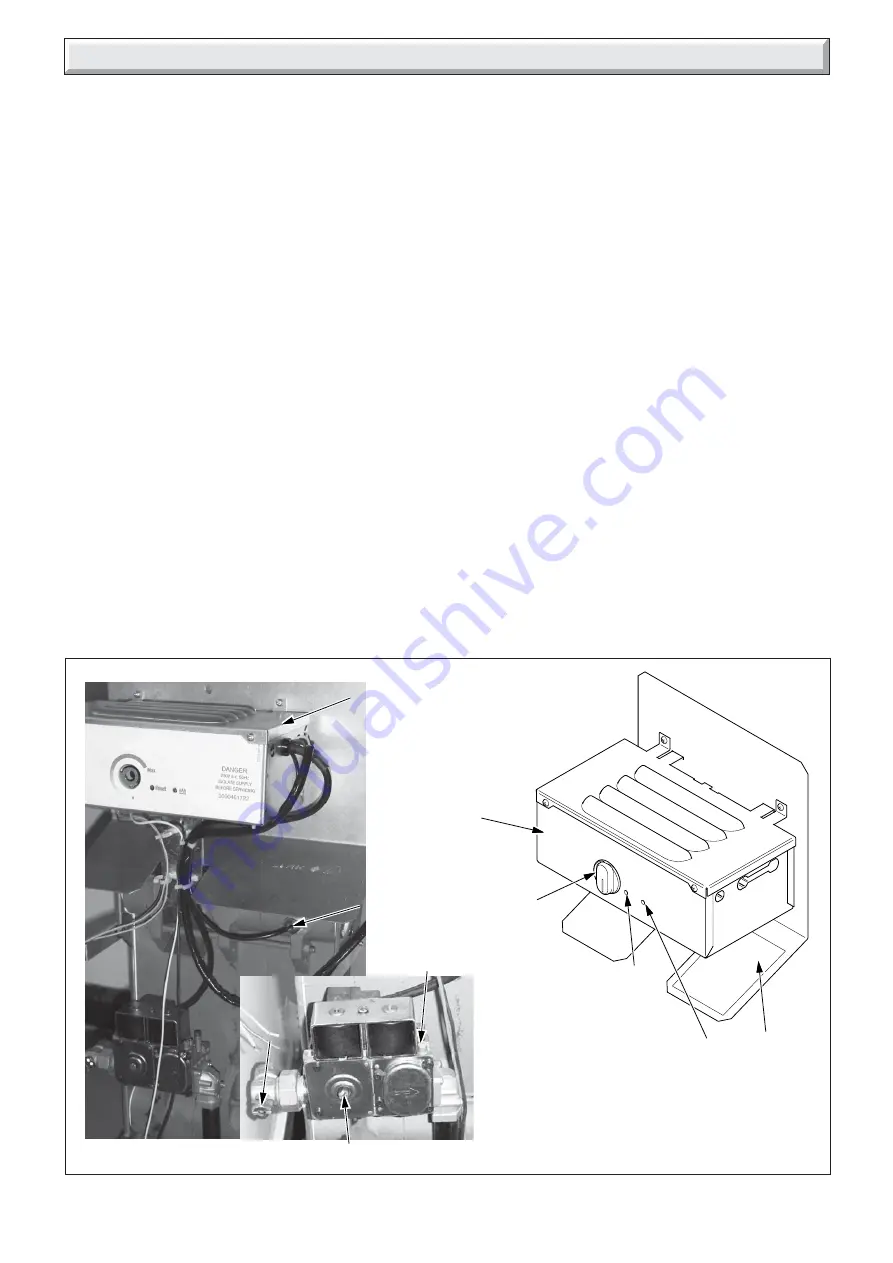
Diagram 6.1
BOILER COMPONENTS
10052
A CONTROL BOX
B PHIAL POCKET
C GAS SERVICE COCK
D "BURNER ON" NEON
E RESET NEON
F TEMPERATURE CONTROL
G BURNER PRESSURE TEST POINT
H GAS PRESSURE ADJUSTMENT SCREW
J DATA LABEL
E
D
A
G
Turn the boiler temperature control clockwise to “Max”.
The ignition system will operate to light the boiler. After a pre-
set time if ignition has not taken place the boiler will shutdown.
To re-start the lighting sequence, turn the boiler temperature
control to “O”, then fully clockwise to “Max”.
"Max" is approximately 82
°
C (180
°
F).
After the burner has lit, the “Burner on” neon on the control panel
will come on.
Isolate the boiler from the electrical supply.
Loosen the burner pressure test point screw and connect a
suitable pressure gauge, see diagram 6.1.
Switch on the electrical supply to the boiler.
WARNING. The multifunctional control and fan operate on
mains voltage, terminals will become live.
6.3 Testing - Electrical
Turn the boiler temperature control fully clockwise to the
maximum setting.
The lighting sequence is automatic as follows:
The fan operates and after a short period of time, the spark
ignition operates, the solenoid opens, then the burner will light
shown by the “Burner On” neon on the control panel lighting up.
The burner will remain alight until switched off, either by the
boiler temperature control, programmer (if fitted) or any remote
system control.
To make sure that the flame supervision device is working
correctly the following should be done.
With the burner alight, turn the gas service cock “Off”, see
diagram 6.1.
F
B
C
H
A
0000
J


