24
221992D
FUSE
TYPE F4A
AIR PRESSURE
SWITCH CONNECTIONS
FAN
EV1
EV2
SPARK
ELECTRODE
AIR
PRESSURE
SWITCH
SL
(N/O) (C)
(N/C)
br
br
bk
p
r
gy
y
br
bk
KEY
bk BLACK
br BROWN
b BLUE
p PURLPLE
r RED
y YELLOW
gy GREY
MAIN TERMINAL
STRIP CONNECTIONS
PRINTED CIRCUIT
BOARD CONNECTIONS
b
b
b
N
b
N
MAINS SUPPLY
230v ~ 50Hz
9.1 Electrical
Gain access to the control box, refer to the relevant paragraph
in section 8.1, then remove the control box cover, refer to
section 5.1.
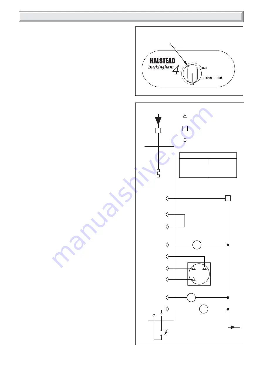
Refer to: Boiler Fault Finding, see diagram 9.1, Fault Finding
Wiring Diagram, see diagram 9.3, Pictorial Wiring Diagram, see
diagram 9.4.
9.2 Electrical Supply Failure
Failure of the electrical supply will cause the burner to go out.
Operation will normally resume on the restoration of the electrical
supply.
If the burner does not relight after an electrical supply failure and
the red neon on the control panel is lit, turn the burner temperature
control to “0”, wait 30 seconds, then fully clockwise to “Max.”
see diagram 9.2.
Diagram 9.3
10084
9 Fault Finding
Diagram 9.2
BOILER TEMPERATURE
CONTROL
10169


