28
221992D
Because of our constant endeavour for improvement, details may vary slightly from those shown in these instructions.
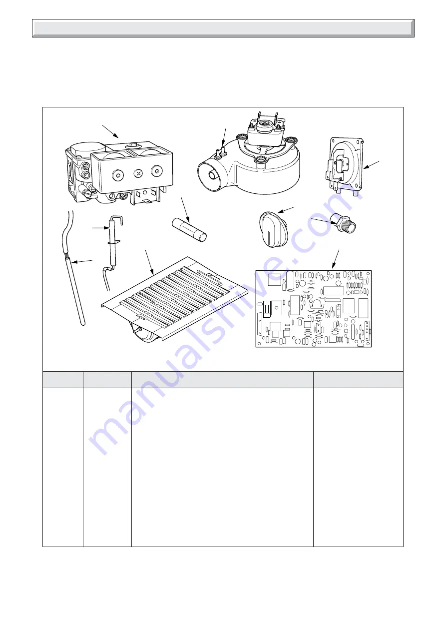
Diagram 11.1
11 Spare Parts
10177
3
6
9
7
2
4
5
1
8
11.1 Part Identification
The key number in diagram 11.1 and the first column of the list
will help identify the spare part.
11.2 Ordering
When ordering any spare part please quote the part number
and the description from the list together with the model name
and serial number information from the data label.
The data label is positioned on the heat shield, see diagram 6.1.
Key No.
Part No.
Description
GC Part No.
1
2000461752
Multifunctional control
******
2
227132
Fan
******
3
2000461994
Air pressure switch
******
4
2000461985
Electrical thermistor
******
5
202635
Spark electrode
******
6
2000461714
Boiler temperature control knob
******
7
2000461924
Injector
******
8
227098
Fuse
******
9
227030
Control board
******
10
205656
Burner
******
10


