Supplied By www.heating spares.co Tel. 0161 620 6677
10
3.3
FLUE TERMINAL POSITION
Detailed recommendations for flue installation are given in
BS 5440:1. The following notes are for general guidance.
a)
The boiler MUST be installed so that the terminal is exposed to
the external air.
b)
It is important that the position of the terminal allows free
passage of air across it at all times.
c)
It is ESSENTIAL TO ENSURE that products of combustion
discharging from the terminal cannot re-enter the building, or
any other adjacent building, through ventilators, windows,
doors, other sources of natural air infiltration, or forced
ventilation / air conditioning.
d)
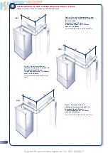
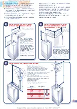
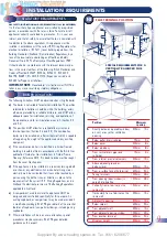
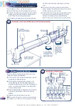
The minimum acceptable dimensions from the terminal to
obstructions and ventilation openings are specified in Fig.12.
e)
If the terminal discharges into a pathway or passageway
check that combustion products will not cause nuisance and
that the terminal will not obstruct the passageway.
f)
Where the lowest part of the terminal is fitted less than 2m
(78ins) above ground, above a balcony or above a flat roof to
which people have access, the terminal MUST be protected by
a purpose designed guard. (Available as an optional extra)
g)
Where the terminal is fitted within 850mm (34in) of a plastic
or painted gutter, or 450mm (18in) of painted eaves, an
aluminium shield at least 750mm long must be fitted to the
underside of the painted surface.
h)
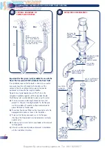
The air inlet / flue outlet duct MUST NOT be closer than
25mm (1in) to combustible material.
i)
In certain weather conditions the terminal may emit a plume
of steam. This is normal but positions where this would cause
a nuisance should be avoided.
Detailed recommendations for air supply are given in BS 5440:2.
The following notes are for general guidance.
a)
It is not necessary to have a purpose provided air vent in the
room or internal space in which the appliance is installed.
b)
If the boiler is to be installed in a wall cupboard permanent air
vents are required for cooling purposes in the cupboard at both
high and low levels. Both air vents must communicate with either
the same internal room / space or be on the same wall to
external air. Each air vent communicating with another room or
internal space must have a minimum effective area of:
Finest - 298cm
2
(46in
2
)
Finest Gold - 337cm
2
(52in
2
)
If the ventilation is direct to air from outside the building, the
necessary areas quoted above may be halved.
If the cupboard or compartment is full room height (2.3 m min.)
then NO purpose made ventilation is required.
3.5
GAS SUPPLY
a)
The Gas Supplier should be consulted at the installation
planning stage in order to establish the availability of an
adequate supply of gas.
b)
An existing service pipe MUST NOT be used without prior
consultation with the Gas Supplier.
c)
A gas meter can only be connected by the Gas Supplier or by
their contractor.
d)
An existing meter and/or pipework should be of sufficient size
to carry the maximum boiler input plus the demand of any
other installed appliance. (BS 6891: 1988).
A minimum of
22mm dia. pipework is required to within 1 metre of
the appliance gas cock.
e) Natural gas appliances:
The governor at the meter must
give a constant outlet pressure of 20mbar (8 in.wg) when all
appliance’s on the system are running.
Propane appliances:
The regulator must give a constant
outlet pressure of 37 mbar (14.9 in.wg) when all appliance’s
on the system are running.
f)
The gas supply line should be purged. WARNING: Before
purging open all doors and windows, also extinguish any
cigarettes, pipes, and any other naked lights.
g)
The complete installation must be tested for gas soundness .
3.6
CENTRAL HEATING SYSTEMS
a)
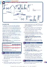
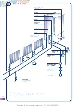
This appliance is designed for connection to sealed central heat-
ing water systems. Refer to Fig. 15 for a typical system design.
b)
A sealed system must only be filled by a competent person. A
filling loop is supplied as an integral part of the boiler, there-
fore no special connections are needed within the system.
Instructions for filling the system using the integral filling loop
are supplied in section 5.
c)
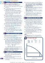
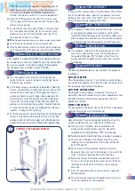
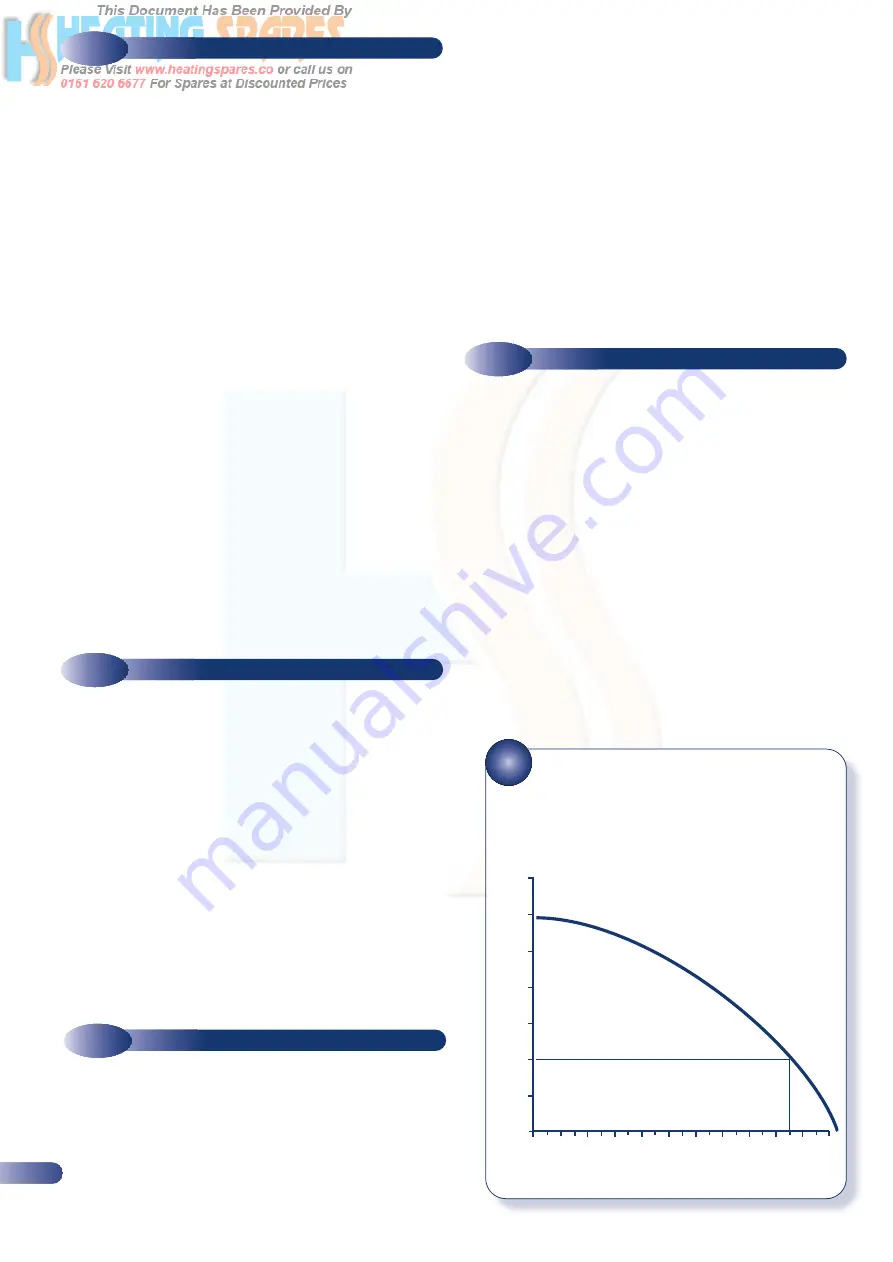
The available pump head is given in Fig. 13.
d)
A minimum heating flow rate corresponding to a heating
differential of 15°C must be obtained at all times.
e)
An automatic heating bypass is fitted within the appliance.
However if thermostatic radiator valves are fitted, a radiator
must be fitted with two lockshield valves.
f)
The following paragraphs outline the specifications of the
items fitted to the boiler.
PUMP
The available head shown in Fig. 13 is that in excess of the
appliance hydraulic resistance, i.e. that available for the system.
13
AVAILABLE PUMP HEAD
3.4
VENTILATION REQUIREMENTS
0
2
4
6
8
10
12
14
16
18
20
22
7
6
5
4
3
2
1
Flow Rate ltr/min
A
vailable Head Metres
2m HEAD
Bth/hr.
Kw
Flow rate
∆
t°C
80,000
23.45
19l/m
17.7
70,000
20.52
19l/m
15.5
60,000
17.58
19l/m
13.3
50,000
11.72
19l/m
8.8


