Supplied By www.heating spares.co Tel. 0161 620 6677
36
MULTIFUNCTIONAL GAS CONTROL
9.7
PRESSURE SWITCH
9.8
OVERHEAT THERMOSTAT
9.9
PCB
9.10
CH/DHW MICROSWITCH
37
OVERHEAT THERMOSTAT
3)
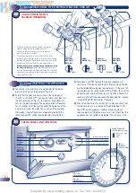
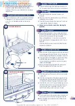
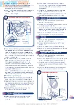
Using a 10mm spanner, turn brass nut ‘B’ to attain the
required minimum burner pressure (as stated in section 2.2 or
on the data plate. Turn the nut clockwise to increase or
anticlockwise to decrease the pressure.
4)
Check that the minimum pressure is correctly set by turning on
and off the DHW tap several times and on each occasion
allowing the burner to ignite.
5)
Isolate the mains electricity supply and re-connect the two
modureg leads. (polarity is immaterial). Restore the electricity
supply and fully open any hot water tap to ensure that the
flow rate is high to prevent modulation. (Note ignition should
occur in the region of 6 mbar (2.4 in.wg) burner pressure and
increase to maximum rate.)
6)
Set the MAXIMUM DHW pressure (as detailed on the data
plate or in section 2.2) by holding nut ‘B’ in position with a
10 mm spanner and rotating plastic nut ‘A’ with a 7 mm
spanner until the correct pressure is obtained. Turn the nut
clockwise to increase or anticlockwise to decrease the pressure.
It is essential that the MINIMUM pressure has been set prior to
adjusting the MAXIMUM pressure.
Check that the MAXIMUM pressure is correctly set by turning
on and off the DHW tap several times and on each occasion
allowing the burner to ignite and increase to the maximum level.
7)
Refit the modureg unit sealing cap.
8)
Reduce the DHW draw off rate progressively and check that the
burner pressure reduces in response to DHW temperature rise.
9)
Close the DHW tap and ensure that the burner is extinguished
and the pump stops (after a brief overrun period). Remove the
pressure gauge, open the DHW tap to re-light the burner and
test for gas soundness.
10)
Close the DHW tap, re-assemble the control panel and
casing, then set all boiler controls as required.
a)
Remove the casing panels and lower the control box as
described in section 9.1 step (a).
b)
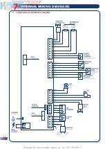
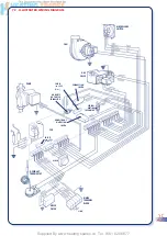
Unclip all electrical connector plugs from the PCB (Refer to
section 7, 7.1).
c)
Remove the six screws securing the plastic PCB housing.
d)
Remove the PCB, transfer the plastic knobs onto the new PCB
and re-assemble in reverse order.
a)
Remove the casing panels and lower the control box as
described in section 9.1 step (a).
b)
Release the appropriate microswitch assembly from the spindle
by sliding out the retaining spring clip (Refer to figure 38).
c)
Unscrew the three screws fixing the plastic housing halves
together and slide the microswitch forwards to release it from
the housing.
d)
Transfer the electrical connections to the new microswitch, fit
the new microswitch and re-assemble in reverse order.
a)
Remove the casing front panels as described in section 9.1
step (a) and remove the sealed chamber front panel
(4 screws).
a)
Remove the casing panels and lower the control box as
described in section 9.1 step (a).
b)
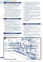
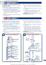
Unclip the thermostat phial from the pipe, and disconnect the
two electrical connections (Fig. 37).
c)
Unscrew the four screws (underneath) securing the appliance
baseplate and control box. Carefully support the control box
and unscrew the nut securing the overheat thermostat.
d)
Replace the thermostat and re-assemble in reverse order.
Ensure that the phial is correctly clipped onto the pipe.
b)
Disconnect the pressure sensing pipes from the pressure
switch (note that the short pipe (from the flue gas sampling
point) is connected to the rear (-ve) connection on the
pressure switch).
c)
Unscrew the two screws securing the pressure switch, and
transfer the electrical connections to the new switch.
d)
Fit the new pressure switch and re-assemble in reverse order
referring to the wiring diagrams (section 7) if necessary.
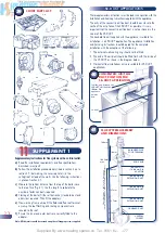
ELECTRICAL
CONNECTOR PLUG
UNION NUT
INLET FLANGE
SCREWS (4)
INLET PRESSURE
TEST POINT
BURNER PRESSURE
TEST POINT
NUT ‘A’
NUT ‘B’
MODUREG
MODUREG
LEADS
PHIAL
PIPE CLIP
ELECTRICAL
CONNECTIONS
SECURING NUT &
OVERHEAT RESET BUTTON
29

