Supplied By www.heating spares.co Tel. 0161 620 6677
9.15
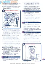
PUMP
9.16
PRESSURE RELIEF VALVE
9.18
AUTO AIR VENT
9.17
PRESSURE GAUGE
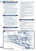
9.19
CH EXPANSION VESSEL
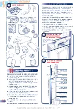
SHORT PARTS LIST
10
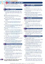
a)
Remove the casing panels and lower the control box as
described in section 9.1 steps (a) and (b).
b)
Turn the CH flow and return valves to the closed position to
isolate the boiler (see section 5.1), then drain the appliance
using the drain cock provided on the CH flow valve.
c)
Remove the screw securing the electrical connections cover on
the pump, and remove the electrical connections.
d)
Either unscrew the two pump unions and remove the entire
pump (using new sealing gaskets) OR unscrew the four socket
head cap screws and remove the pump head only.
e)
Replace the pump (or pump head), re-assemble in reverse
order, and re-commission the system as explained in section 5.
a)
Remove the casing panels and lower the control box as
described in section 9.1 step (a).
b)
Turn the CH flow and return valves to the closed position to
isolate the boiler (see section 5.1), then drain the appliance
using the drain cock provided on the CH flow valve.
c)
Unscrew the union connections to the pressure relief valve,
and remove the valve.
d)
Replace the valve, re-assemble in reverse order, and
re-commission the system as explained in section 5.
a)
Remove the casing front panels and sealed chamber front
panel as described in section 9.1 step (a).
b)
Remove the combustion chamber front panel and burner
locating bracket (7 screws). Take care not to damage the
insulation.
c)
Turn the CH flow and return valves to the closed position to
isolate the boiler (see section 5.1), then drain the appliance
using the drain cock provided on the CH flow valve.
d)
Remove the plastic pipe from the top of the air vent, and
unscrew the auto air vent using a suitable pipe wrench.
e)
Fit replacement and re-assemble in reverse order.
a)
Remove the casing panels and lower the control box as
described in section 9.1 step (a).
b)
Turn the CH flow and return valves to the closed position to
isolate the boiler (see section 5.1), then drain the appliance
using the drain cock provided on the CH flow valve.
c)
Unscrew the pressure gauge connection from the valve
assembly, unclip the pressure gauge head out of the fascia
panel, and remove the pressure gauge.
d)
Replace the pressure gauge, re-assemble in reverse order,
and re-commission the system as explained in section 5.
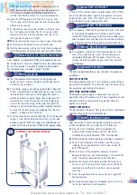
In the unlikely event of failure of the expansion vessel diaphragm
it is acceptable to leave the vessel in position and to fit a
replacement vessel (of similar or greater capacity) external to the
appliance but as close as possible to the CH return.
To replace the expansion vessel it is necessary to isolate the
central heating system from the appliance, drain the appliance
and multifunctional boiler chassis then remove the appliance from
the multifunctional boiler chassis and drain the central heating
system. The vessel can then be unscrewed and replaced.
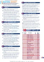
9.20
OPTIONAL TIME CLOCK
a)
Remove the casing panels and lower the control box as
described in section 9.1 step (a).
c)
Remove the six screws securing the plastic PCB housing and
carefully lift it clear of the front panel, to expose the timer
fixing screws.
d)
Unscrew the four timer fixing screws, transfer the wires to the
new timer (referring to the wiring diagrams in section 7 if
necessary), and re-assemble in reverse order.
NOTE:
Should an external time clock be used with the appliance, the internal
clock may be replaced with a switch which is available as an optional extra. If the
clock is to be powered from the appliance connection (terminal 5) then the switch
should be kept ON to maintain a permanent live supply to the clock motor.
Alternatively the intergrated clock can be switched to permanently ON, or the red
jumper on the PCB can be positioned to NO CLOCK POSITION.
f)
Remove the switch body by sliding to the right.
g)
Replace the flow switch and re-assemble in reverse order.
Ensure that the alignment pin is correctly aligned.
Recommission the hot water system as explained in section 5.
Key G C Part
Description
No
Makers
No.
off Pt
No.
1
BURNER (Natural gas)
1
700535
2
BURNER (Propane gas)
1
700538
3
INJECTOR (Natural gas)
1
700536
4
INJECTOR (Propane gas)
1
700537
5 IGNITION
ELECTRODE
1
500588
6 DETECTION
ELECTRODE
1
500589
7 GAS
CONTROL 1
500591
8 PCB
1
500585
9
AIR PRESSURE SWITCH
1
500592
10 FAN
ASSEMBLY 1
988355
11 OVERHEAT
THERMOSTAT
1
550519
12 THERMISTOR
2
500590
13
MAIN HEAT EXCHANGER
1
450978
14
DHW HEAT EXCHANGER
1
450985
15
PRESSURE RELIEF VALVE
1
450987
16
AUTO AIR VENT
1
450908
17 PRESSURE
GAUGE 1
450961
18 PUMP
1
851213
19 MICROSWITCH
ASSEMBLY
2
500593
20
WATER FLOW REGULATOR
1
21
FLOW SWITCH BODY
1
500594
22 EXPANSION
VESSEL
1
450986
23 HEATING
CLOCK 1
600520
300716 STD
300715 GOLD
31

