Supplied By www.heating spares.co Tel. 0161 620 6677
33
SUPPLEMENT 2
12
42
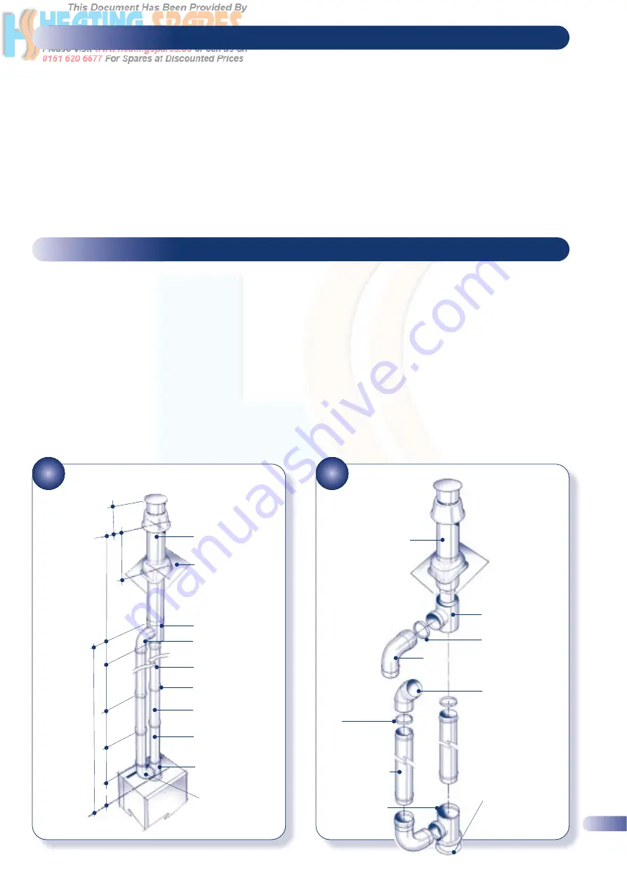
TWIN PIPE SYSTEM DIMENSIONS
43
INSTALLING A TWIN PIPE SYSTEM
SUPPLEMENT 3
13
Supplementary instructions for flue systems incorporating
an additional 90° elbow.
a)
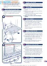
Read and follow the installation procedure described in the
main section of the installation instructions up to section 4.2.
b)
Using the MBC as a template and the dimensional
information given earlier in this booklet determine where the
boiler and flue are to be positioned and make the necessary
hole in the wall(s) for the air/flue duct as defined in
section 4.2.
c)
Install the boiler as described in section 4 with the exception
of the flue system (4.7)
Supplementary instructions for twin pipe flue systems.
a)
Read the installation requirements and flue specifications
described in section 3 but refer to section 2.7 page 6 if a twin
pipe flue system is to be fitted.
b)
Using the MBC as a template and the dimensional
information given earlier in this booklet determine where the
boiler and flue are to be positioned and make the necessary
holes in the wall(s) for the air/flue duct as defined in
Figure 42.
c)
Install the boiler as described in section 4 with the exception
of the flue system (4.7).
d)
Using the information and dimensions in Figure 42 and
earlier in this booklet calculate the lengths required for each
duct.
e)
Cut each duct to length, ensuring that each cut is square and
free from burrs.
f)
Install the flue terminal by first lifting the roof flashing in
position in the roof. Then inserting the terminal from above,
down through the flashing. The two plastic parts will mate
together to form a seal. Continue assembling the ducts
downwards, working back to the boiler as shown in Figure 42
IMPORTANT NOTE:
All flue joints must be secured by two self-tapping
screws through the air duct as illustrated.
d)
Using the information and dimensions in Figure 41 and
earlier in this booklet calculate the lengths required for each
duct.
e)
Cut each duct to length, ensuring that each cut is square and
free from burrs.
f)
Install the flue terminal as described in section 4.7, then
starting at the terminal end assemble the ducts as shown in
Figure 42, and work back towards the boiler.
IMPORTANT NOTE:
All flue joints must be secured by two self-tapping
screws through the air duct as illustrated.
BALANCED FLUE
ROOF TERMINAL
ROOF LINE
T-ADAPTOR
90° 80mm DIA.
SWEPT ELBOW
80mm DIA.
STANDARD DUCT
SEALS AT ALL
JOINTS
80mm DIA.
STANDARD DUCT
80mm DIA.
STANDARD DUCT
T-ADAPTOR
FLANGED
90° 80mm DIA.
SWEPT ELBOW
180mm
430mm
718mm
160mm
1000mm
1000mm
1000mm
160mm
Finest P
ropane Max = 9.0M. If over 7M insulate ducts in roof space.
M/F 45° SWEPT ELBOW
EQUIV. LENGTH 0.8M
PART No. 840510
80/118mm DIA.
VERTICAL FLUE
TERMINAL
PART No. 840506
ADAPTOR TWIN PIPE
TO VERTICAL
TERMINAL
PART No. 840509
SEAL (FITTED)
IN ADAPTOR
M/F 90° SWEPT ELBOW
EQUIV. LENGTH 1.5M PART No. 840507
FIBRE SEAL
SUPPLIED WITH
APPLIANCE &
ALWAYS FITTED
BETWEEN
APPLIANCE AND
T-ADAPTOR OR
FLANGED ELBOW
FLANGED
T–ADAPTOR
PART No.
840511
80mm DIA.
M/F 1m
EXT. DUCT
PART No. 840508
SEAL FITTED
IN DUCT AT
FEMALE END
F
F
F
F
F
F
F
M
M
M
M
M
M
M

