14
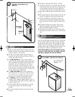
4.3.4
a)
The vertical flue terminal kit (Part No: 988378) contains full
assembly details.
b)
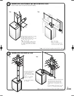
Measure the vertical distance from the top of the appliance to
the roof line (Fig 20), and calculate the extension ducts
required.
c)
Starting at the boiler, fit the vertical flue socket with gasket, the
standard duct and the required extensions. Ensure all ducts
are engaged correctly and secured using the self-tapping
screws provided in the kits.
d)
Fit the vertical flue terminal adaptors.
e)
Working from outside the building, fit the vertical flue terminal
ensuring correct engagement of the inner and outer ducts into
the flue adaptors.
f)
Ensure that the roof flashing and sealing components are
secured to the roof.
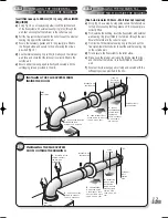
PREPARING AND INSTALLING
THE VERTICAL DUCT
FLUE SYSTEM ASSEMBLY
AND DIMENSIONS
20
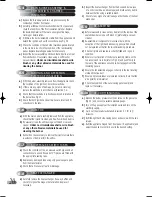
4.4
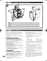
Connect the gas supply to the
1/2
inch BSPF (located at the
bottom, right hand side of the appliance) isolation valve using a
suitable jointing compound. (Fig 21.)
GAS CONNECTION
4.5
a)
Refer to section 3.8 for detailed information.
b)
The appliance is supplied with two 22mm copper tail ends
suitable for compression or soldered fittings.
Use extreme
care if soldering joints near to the appliance. If
boiler is located in tight space it is recommended to
remove the pipes from the boiler.
c)
The system
FLOW
must be connected to the
UPPER PIPE
.
The system
RETURN
must be connected to the
LOWER PIPE
.
Note: It is recommended to connect Hero 90 to
28mm system pipes.
WATER CONNECTIONS
PIPEWORK
21
•
BALANCED FLUE
ROOF TERMINAL
•
ROOF LINE
•
100/60mm TO
118/80mm DIA
ADAPTOR
•
100/60mm DIA
EXTENSION DUCT
•
100/60mm DIA
EXTENSION DUCT
•
100/60mm DIA
EXTENSION DUCT
•
STANDARD DUCT
•
VERTICAL
SOCKET
•
425mm
•
•
50mm
767mm
767mm
•
•
•
•
•
•
767mm
30mm
1046mm
max
430mm
180mm
MAIN GAS
INLET
FLOW
PIPE
RETURN PIPE
•
•
•
•
Hero 1/03 TO PRINT 8/5/03 10:45 am Page 14

