background image

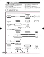
FLOW CHART 1: START/POWER UP FAULT FINDING

SHORT PARTS LIST

10

Key 

G C Part No.

Description 

Boiler

No off 

Makers Pt No.

1

E96-047 

SIGMA GAS VALVE

1

500623

E96-048 

ANALOG PCB assy (incl. cover, knob and bezel)

1

988442

3a

E96-049 

AIR PRESSURE SWITCH 40/75

500625

3b

E96-050

AIR PRESSURE SWITCH 60/60P

1

500631

3c

E96-051 

AIR PRESSURE SWITCH 30/50

500627

3d

E96-052 

AIR PRESSURE SWITCH 90 

500628

3e

E96-053

AIR PRESSURE SWITCH 40P 

500629

4

E96-054 

THERMISTOR 

500626

5

E96-055 

ELECTRODE 

500630

6a

E96-056 

BURNER 30/40

700580

6b

E96-057 

BURNER 50/60

700581

6c

E96-058 

BURNER 75/90 

700582

7a

E96-059

FAN - HERO 50/60

1

601009

7b

E96-060 

FAN - HERO 30/40

601010

7c

E96-061 

FAN - HERO 75/90 

601011

8

E96-062 

CLIP ON OVERHEAT STAT

550527

9a

E96-063 

INJECTOR HERO 30/40

700590

9b

E96-064

INJECTOR HERO 50

1

700592

9c

E96-065

INJECTOR HERO 60

1

700593

9d

E96-066

INJECTOR HERO 75 

700594

9e

E96-067

INJECTOR HERO 90

700595

25

1

2

9a - 9e

3a - 3e

8

7a - 7c

4

6a - 6c

5

Halstead Hero cover  8/5/03  8:39 am  Page 4

Summary of Contents for Hero 30

Page 1: ...87 BN 41 Installation and Service Instruction To be left with user adjacent to gas meter G C APPLIANCE No Hero 30 41 260 01 Hero 60 41 260 04 Hero 40 PROPANE 41 260 07 Hero 40 41 260 02 Hero 75 41 260...

Page 2: ...British standard BS7593 1992 stresses the importance of cleansing and flushing of the system to ensure it continues to run efficiently with the minimum of maintenance necessary Halstead Boilers fully...

Page 3: ...27 2 32 6 BTU h 37020 49372 49372 61757 74040 74040 92806 111231 kW 9 78 13 03 13 33 16 3 19 6 19 99 24 51 29 37 BTU h 33369 44458 45495 55616 66875 68226 83628 100210 mbar 6 9 12 2 21 5 10 0 12 5 23...

Page 4: ...all thickness up to 330mm For wall thicknesses in excess of 330mm use Rear Flue extension duct 955081 Dimension as shown in Fig 2a The following additional concentric flue kits are also available as o...

Page 5: ...application flue kit 955080 is required Note For vertical flue application flue kit 955082 and 988378 is required X1 X2 X1 365 820mm X2 270 820mm measured from the boiler outlet centre line to the out...

Page 6: ...nstallation with the exception of the following a The external wall flue sealing ring shall not be used b Only horizontal flue installations are suitable for SE DUCT applications c The minimum wall th...

Page 7: ...ace facing the terminal 600mm 24in I Facing terminals 1200mm 48in J From opening door window in 1200mm 48in carport into dwelling K Vertically from a terminal on the 1500mm 60in same wall L Horizontal...

Page 8: ...m or internal space must have a minimum effective area of 5625 mm2 Top and Bottom 3 5 GAS SUPPLY a The Gas Supplier should be consulted at the installation planning stage in order to establish the ava...

Page 9: ...ose to the inlet side of the pump and must suit the water volume of the system The volume of water in the appliance is given in Section 2 The system pressure should be not less than the static height...

Page 10: ...PLIANCE 22mm COPPER 15mm COLD FEED OPEN VENT FEED AND EXPANSION TANK MINIMUM HEAD 1 2m Fit either two motorised valves or one 3 way motorised valve MAKE UP BOTTLE Observe minimum static head requireme...

Page 11: ...uct through the hole from inside of the room and ensure that the seal is seated properly on the outer wall j Ensure that a full 30mm protrudes from the inside wall drill through the air duct and fixin...

Page 12: ...ER ONTO WALLBRACKET 17 12 FITTING THE ADAPTOR TUBE TO FAN FLUE ADAPTOR FLUE TERMINAL FAN TO REMOVE FRONT PANELS UNSCREW THE SIX SCREWS 13 FITTING THE FLUE RESTRICTOR RESTRICTOR FAN ALUMINIUM FAN OUTLE...

Page 13: ...ickness is less than 800mm 31 in the air flue duct may be fitted without access to the external wall providing that the optional wall liner is used This is necessary to seal any cavity and to allow th...

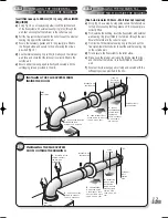
Page 14: ...m before securing the ducts f Prior to fitting the standard flue duct to the flanged elbow ensure all O ring seals are correctly located and intact g All ducts should be secured by drilling two 3 3mm...

Page 15: ...erminal is the correct way up c From inside fit the internal sealing ring white and pull the flue system towards the boiler to seat the external sealing ring on the outside wall d Fit and secure the f...

Page 16: ...NSIONS 20 4 4 Connect the gas supply to the 1 2 inch BSPF located at the bottom right hand side of the appliance isolation valve using a suitable jointing compound Fig 21 GAS CONNECTION 4 5 a Refer to...

Page 17: ...WIRING INSTRUCTIONS L1 L2 N L3 If using 6 wire 28mm or 1 BSPV4043H on any circuit white is not needed and must be made electrically safe The wiring shown is based on the use of 10 way junction box Hon...

Page 18: ...mp live 1 Switched live L Permanent live ST6400 ST6300 ST6200 7 6 4 3 2 1 E N L L N E 2 1 T6360B Room thermostat 230V 50Hz Pump Boiler L2 L3 E N L1 T6360B Room thermostat L641A Cylinder thermostat 2 1...

Page 19: ...o maximum e Turn on the electrical supply and check the pump is working and water is circulating through the system f Turn the appliance control thermostat device fully clockwise to the maximum settin...

Page 20: ...provided 30 5 3 USERS INSTRUCTRIONS Upon completion of commissioning and testing the system the installer should draw the user s attention to the following a Give the Users Instructions to the househo...

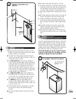
Page 21: ...ws securing the right hand side casing panel and slide forwards to disengage d Isolate the gas supply at the isolation valve situated at the bottom right hand side of the appliance COMMENCING WITH SER...

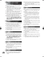
Page 22: ...er c It should not be necessary to remove the injector unless there is evidence of debris within the orifice INJECTOR 6 7 a Check the condition of the air pressure switch pipes and all connections are...

Page 23: ...SSURE SWITCH a Disconnect the 3 electrical connections from the switch b Disconnect the sensing tubes from the switch c Unclip the air pressure switch from the mounting bracket by pulling the bottom o...

Page 24: ...owing burner location on the runners and tie rods Push firmly to the rear of the appliance and ensure correct engagement of the insulation panels 7 6 MAIN BURNER a See note after section 7 4 b Remove...

Page 25: ...out procedures detailed in section 7 6 points a to e inclusive b Replace the insulation panel s and re assemble the appliance in reverse order taking note of point g of section 7 6 INTERNAL WIRING DI...

Page 26: ...stor s resistance The resistance should be between 14 k 2 5 Kohms Faulty PCB Replace Faulty Thermistor Replace Is there 230V ac on the fan Isolate the electrical supply and gain access to the fan Swit...

Page 27: ...0 1 500628 3e E96 053 AIR PRESSURE SWITCH 40P 1 500629 4 E96 054 THERMISTOR 1 500626 5 E96 055 ELECTRODE 1 500630 6a E96 056 BURNER 30 40 1 700580 6b E96 057 BURNER 50 60 1 700581 6c E96 058 BURNER 75...

Page 28: ...co uk or service halsteadboilers co uk or training halsteadboilers co uk Website www halsteadboilers co uk SERVICE HELPLINE 01926 834834 TRAINING INFORMATION 01926 834838 Halstead Boilers are continu...

Reviews: