4
Important Note~ The HERO 30 IS NOT SUITABLE FOR SE-DUCT
APPLICATIONS.
SE-Ducts should conform to the requirements of BS 5440 part
1:2000 clause11.
The entry of the concentric air / flue duct should be as close to the
centre of the entry face of the SE-DUCT as possible. It is very
important that the concentric air / flue duct is not positioned in the
corner of the SE-DUCT.
The terminal flue duct kit supplied with the appliance is suitable for
installation in a SE-DUCT application. The Installation and
Servicing Instructions should be used for the complete installation
with the exception of the following:
a)
The external wall flue sealing ring shall not be used.
b)
Only horizontal flue installations are suitable for SE-DUCT
applications.
c)
The minimum wall thickness flue length shall not be less
than 100mm.
d)
The maximum wall thickness flue length shall not exceed
820mm. NOTE~ The HERO 90 is only suitable for a
maximum wall thickness flue length of 620mm.
e)
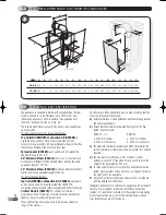
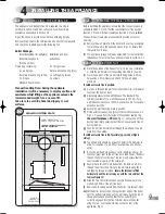
It is important when installing the flue terminal duct into the
SE-DUCT that:
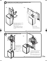
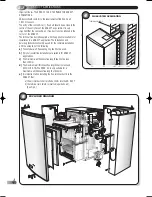
a) the air inlet duct shall protrude 10mm into the SE- DUCT
b) the terminal rain shield is inverted (up-side down).
(See Fig 4)
17
4
FLUE SYSTEM APPLICATION
2.7
SE-DUCT APPLICATIONS
8
EXPLODED DIAGRAM
(for key no. references see spare parts catalogue)
5
Hero exploded
TERMINAL RAIN SHIELD
•
Hero 1/03 TO PRINT 8/5/03 10:45 am Page 4

