Instruction Manual HIPERDRIVE with EtherCAT
8
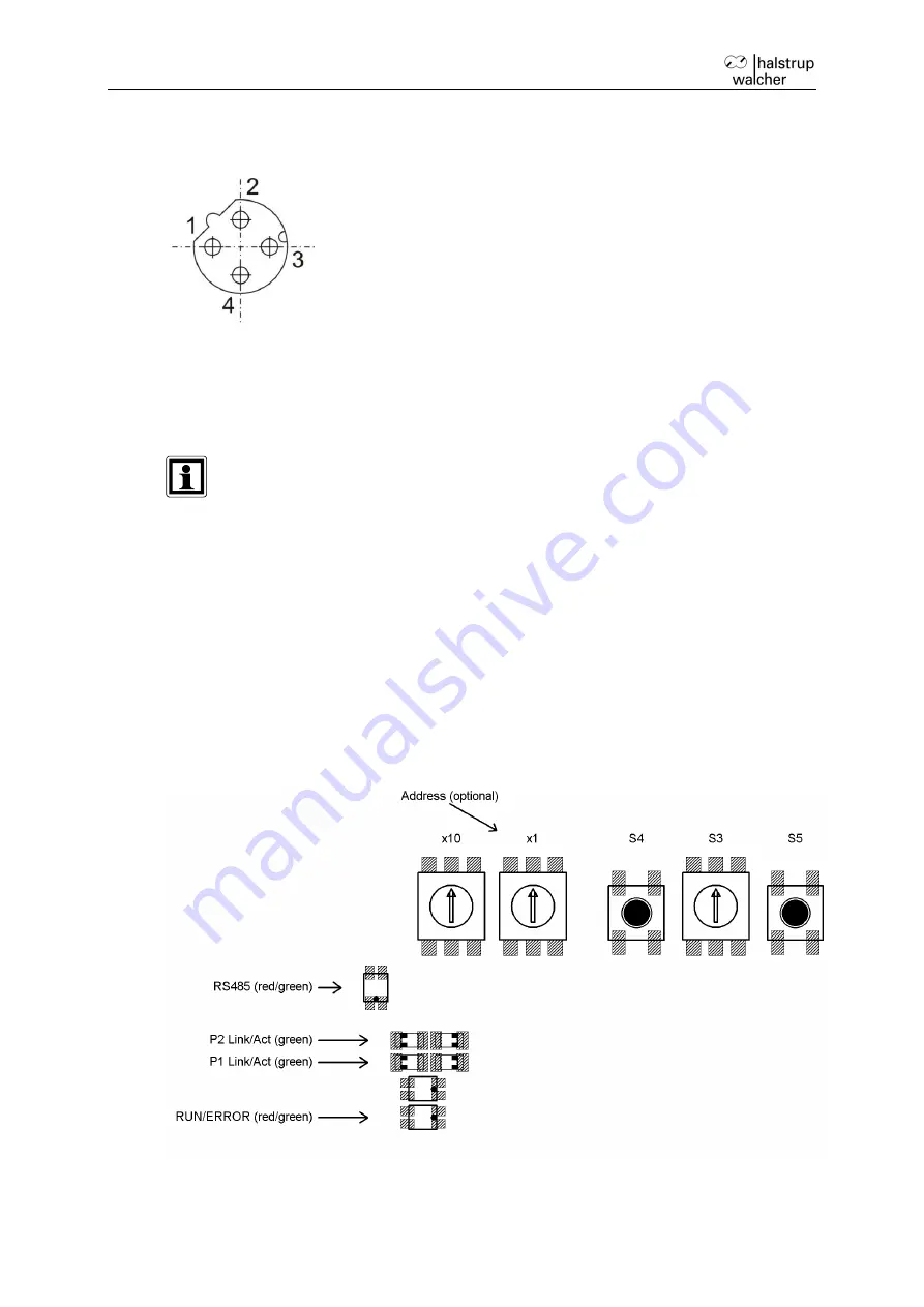
Round sockets for the bus:
(External top view)
1
TD+ (WH/GN, white/green)
2
RD+ (WH/OR, white/orange)
3
TD- (GN, green)
4
RD- (OR, orange)
Due to the use of 4-pin sockets, only four-wire cables should be used.
3.2 Setting the device address
The device address is assigned via the bus of the EtherCAT master.
Alternatively, the
“configured station alias” can be defined using the two rotary switches (address
switch value > 0).
3.3 LEDs and jog keys for the HIPERDRIVE Hub
Opening the housing cover on the top side of the hub provides access to the following
operating and observation elements:


