Instruction Manual PSx3xxEIP
11
2.7. LEDs
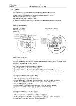
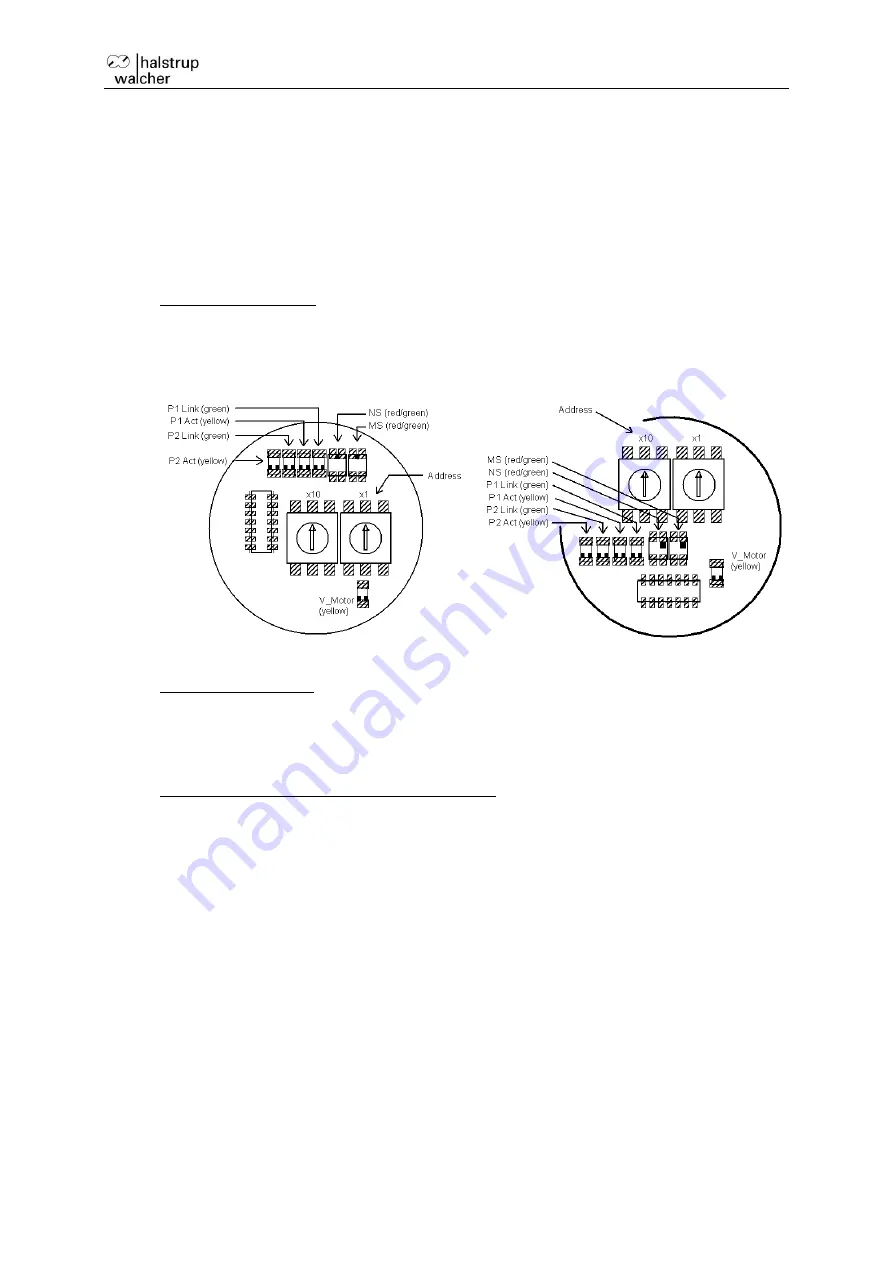
The following LEDs are located under the transparent sealing plug:
P1/P2
: green LINK LEDs and yellow ACT LEDs for ports 1 and 2
MS
: EtherNet/IP Module Status LED
NS
: EtherNet/IP Network Status LED
V_Motor
: The LED is illuminated yellow when power is available to the motor.
Switch configurations:
PSx30x, PSx31x-8,
PSx31x-14, PSx33x,
PSx32x, PSE31xx,
PSE34xx
Meaning of the LEDs:
1) Each of the ports (P1/P2) has two associated LEDs (one green for the
“Link” state
and one yellow for the
“Activity” state).
For each port the following states are possible:
- green off, yellow off
no line connection
- green on, yellow off
line connection is active, no data activity
- green on, yellow is flickering with 10 Hz
line connection is active, data activity
2) red/green
LED “Module Status” (MS)
- off
No power is supplied to the device.
- flashes red/green
Self test (only after power up resp. a reset command)
- flashes red
Minor recoverable fault (e.g. incorrect configuration)
- red on
Major internal fault
- flashes green
Standby (not configured
e.g. no valid IP address)
- green on
operates correctly (e.g. got a valid IP address)
3) red/green L
ED “Network Status” (NS)
- off
no power or no IP address has been assigned
- flashes red/green
Self test (only after power up resp. a reset command)
- flashes red
Timeout of one or more connections


