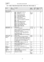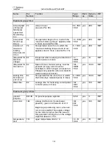
Instruction Manual PSx3xxEIP
9
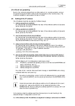
2.5.2. Round socket for bus
connector pattern
(external top view)
assignment
type
1. TD+(WH/GN, white/green)
2. RD+ (WH/OG,
white/orange)
3. TD- (GN, green)
4. RD- (OG, orange)
M12 (D-cod.); 4-pol.
Due to the use of 4-pin sockets, only four-wire cables should
be used.
2.5.3. One Hybrid bushing for supply and bus
connector pattern
(external top view)
assignment
type
1. TD+
2. TD-
3. RD+
4. RD-
5. GND motor
6. GND control unit
7. +24V motor
8. +24V control unit
M12 (Y-cod.); 8-pol.
2.5.4. Connector for jog keys
connector pattern
(external top view)
assignment
type
1. +24V (output)
2. forward key
3. reverse key
4. GND
M8; 4-pol.
2.5.5. Connector-option -2Y-
Two Y-coded bushings for bus and control supply
One A-coded connector for motor supply
connector pattern
(external top view)
assignment
type
1. TD+
2. TD-
3. RD+
4. RD-
5. +24V control unit
6. GND control unit
7. +24V control unit
8. GND control unit
M12 (Y-cod.); 8-pol.
1. +24V motor
2.
3. GND motor
4.
5.
M12 (A-cod.); 5-pol.


