background image


Functions


7100.006424_Bus description_PSD4xx_CA_H_ENG


36


08.04.2020 

4.10 

Reference runs 

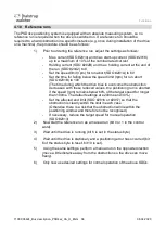
The PSD4xx positioning system is equipped with an absolute measuring system, so no 
reference run is required when the drive is switched on. If a reference run should be 
required to a hard obstruction in a specific instance (e.g. once during installation of the drive 
on a machine), the procedure should be as follows: 

1) 

 Prior to ordering the reference run, adjust the settings as follows: 

Max. current (SDO #2014) and max. start-up current (SDO #2018) 
up to a maximum of 10% of the nominal rated current 

Holding current (SDO #202B) and max. holding current at the end of 
the run (SDO #2042) to 0 

Set the speed limit (rpm) for run abort (SDO #201A) to 60 

Set the time for falling below the speed limit (rpm) for run abort 
(SDO #201B) to 100 
(The time during which the drive tries to overcome the obstruction 
decreases: with these reduced values, the positioning run is aborted 
if the speed (rpm) remains below 60% of the target speed for longer 
than 100ms. The default settings are 200ms and 30%.) 

Set the affected end limit (SDO #2016 or #2017) so that the 
obstruction is clearly within the limit in each case 
(Otherwise there is a risk that the obstruction will lie within the 
positioning window and therefore not be recognised.) 

If necessary, reduce the target speed for manual operation 
(SDO #2013) 

2) 

 Now start the reference run as a manual run (bit 0 or 1 in the control 
word). 

3) 

 Wait until the drive is running (bit 6 is set in the status byte) 

4) 

 Wait until the drive is stationary and a positioning error has occurred (bit 
6 of the status byte is reset, bit 10 is set). 

5) 

 Using the same settings, perform a manual run in the opposite direction 
(move a little distance away from the obstruction so the drive can move 
freely). 

6) 

 Only now use desired settings for normal operation of the above SDOs. 
 

Summary of Contents for PSD4 Series

Page 1: ...Bus description PSD4xx positioning system CANopen...

Page 2: ...pied either wholly or in part or made available to third parties The instruction manual is part of the product Please read this manual carefully follow our instructions and pay special attention to th...

Page 3: ...ts 23 3 6 Detailed description of control bits 27 4 Functions 28 4 1 Types of positioning 28 4 1 1 Positioning run with loop 28 4 1 2 Positioning run without loop 28 4 1 3 Manual run 29 4 2 Start Posi...

Page 4: ...escription is to be used for the commissioning and integration of the drive into a field bus system Technical data for the electrical connections of your drive can be found in the electrical connector...

Page 5: ...mbly can lead to the destruction of the drive WARNING Check that the supply lines are not pinched or crushed Lay the supply lines according to the general and specific local assembly regulations If th...

Page 6: ...units on the respective address switches Turn the device off and on again or use the reset command via the control unit to accept the new setting The device address is now set and the setting is activ...

Page 7: ...ttings and adjust the sliding switches S2 S4 DIP switch 2 4 accordingly Table Baud rate S2 S3 S4 Description OFF OFF OFF Set baud rate via bus default 500 kBaud ON OFF OFF 20 kBaud OFF ON OFF 50 kBaud...

Page 8: ...tor 120 Note For a line topology the bus termination is at both ends of the network The device controls and status elements are located under the sealing plug You will need a non conducting pointed ob...

Page 9: ...cher de technicaldocu The PSD4xx must be grounded before the power supply cable is connected The grounding cable must be connected to the correct position on the PSD4xx and to the ground potential e g...

Page 10: ...0 ms 3 1 Status LEDs The following LEDs are located under the sealing plug Green LED gn RUN LED in accordance with CANopen Single flashes CAN stop Continuous flashing CAN preoperational Continuously i...

Page 11: ...1 and 2 last emergency errors occurred 8 bit 32 bit 0 0 R R Sync ID 1005 COB ID for the sync command 32 bit No 80h R W Comm cycle 1006 Communication cycle time 32 bit No 0 R W Sync window 1007 Synchro...

Page 12: ...of this PDO 8 bit 32 bit No 0 200h device address R R W Sub 2 PDO type 8 bit No 0xFF R W Receive PDO 1 mapping 1600 Sub index 0 No of indices 3 Sub 1 0x20240010 Sub 2 0x00000010 Sub 3 0x20010020 8 bi...

Page 13: ...mm for default values of counters SDO 2010 and denominator SDO 2011 Writing to this index number causes the current position to be referenced to the transferred value 31 bit No R W Referencing value...

Page 14: ...sed for manual runs value in rpm see chap 3 3 16 bit Yes see chap 3 3 R W Maximum current 2014 Applies after the end of the start up phase during start up phase the value 2018 applies value in mA see...

Page 15: ...sec see chap 3 3 16 bit Yes see chap 3 3 R W Deceleration 201D Value in rpm per sec see chap 3 3 16 bit Yes see chap 3 3 R W Loop length 201F Minimum number of increments in which the drive runs to a...

Page 16: ...r bits are reserved and must be set to 0 16 bit No 0 R W Status 2025 Bit 0 Target position reached Bit 1 reserved Bit 2 Togglebit Bit 3 reserved Bit 4 Power available to motor Bit 5 Positioning run ab...

Page 17: ...evolutions current position 4029 revolutions For models with an auxiliary gearbox the range of values is reduced in accordance with the gear ratio 31 bit Yes see chap 3 3 R W Maximum holding current 2...

Page 18: ...Year and week of manufacture given as an integer YYWW 16 bit R Serial number 2041 Device serial number 0 65535 16 bit R Max holding current at completion of run 2042 Max holding current at completion...

Page 19: ...out a start up loop and without positioning in the middle of the measurement range Writing a 3 Resets all parameters to the delivery states without changing the CAN address and baud rate without savin...

Page 20: ...saving the parameters in EEPROM The drive then performs a start up loop and positions itself in the middle of the measurement range Writing a 1 Saves the parameter in EEPROM Writing a 0 No action Rea...

Page 21: ...values Delivery state Upper Limit 2016 805 200 805 200 197 298 805 200 805 200 Lower Limit 2017 805 200 805 200 197 298 805 200 805 200 Target rpm for positioning run 2012 1 800 200 1 500 200 1 250 5...

Page 22: ...1 250 17 Acceleration 201C 1 1587 635 1 1250 500 Deceleration 201D 1 1587 635 1 1250 500 Max operating current 2014 5 4000 1500 5 4000 1500 Max start up current 2018 5 4000 2000 5 4000 2000 Max holdi...

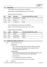
Page 23: ...t be modified Bit Byte Meaning Corresponding SDO index number 0 15 0 1 Status 2025h 16 31 2 3 Current rpm 2030h 32 63 4 7 Actual value 2003h 3 5 Detailed description of status bits Bit 0 Target positi...

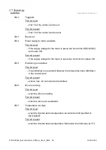
Page 24: ...upply voltage for the motor is below the Umot limit or above 30V Bit 5 Positioning run aborted This bit is set if a positioning run is aborted because the release has been withdrawn in the control wor...

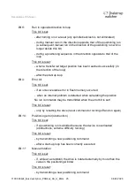
Page 25: ...loop Bit 9 Error bit This bit is set if an unrecoverable error in flash memory occurred when an internal problem is detected when calculating the position No run commands may be transmitted when the...

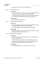
Page 26: ...t if the motor voltage is less than the Umot limit SDO 203C or above 30V when initiating a positioning run or start up loop if the motor voltage leaves the specified range during the run This bit is r...

Page 27: ...ill only be executed if this bit is set This bit must be set for positioning runs and manual runs If this bit is deleted during a run the run will be aborted and status bit 5 Run aborted will be set B...

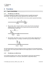
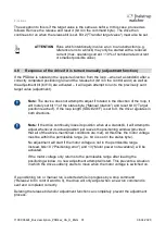
Page 28: ...otation 2a and approaches the exact position after resuming forward motion 2b 3 New position value after reverse run no loop the drive always approaches by moving forward 3b if necessary it will first...

Page 29: ...ransferred control word 0x11 or 0x12 End manual run When a control word is transferred the manual run is stopped Possible are the reset of the manual run control word control word 0x10 or the reset of...

Page 30: ...can be set via SDO 2018 the maximum operating current can be set via SDO 2014 The start up current is active after each run begins for the period defined in SDO 2019 Note The start up current should...

Page 31: ...it will merely set bit 11 of the status byte Manual rotation and reset bit 0 Target position reached If the loop length SDO 201F is set to 0 the drive regulates in both directions Note If the drive c...

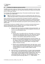
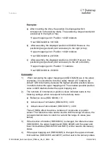
Page 32: ...moved e g a spindle into the desired position run the drive to the appropriate position with the adjustable collar open and only then close the adjustable collar Examples a Bring the axle to be posit...

Page 33: ...gin of 3 rotations by default 1200 increments because the highest possible position value is 3 rotations below the upper mapping end The smallest possible position value is 4029 rotations below the up...

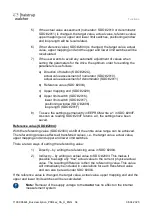
Page 34: ...SDO 2006 loop length SDO 201F 8 To save the settings permanently in EEPROM write a 1 in SDO 204F As soon as reading SDO 204F returns a 0 the settings have been saved Reference value SDO 2004 With the...

Page 35: ...take on values between 1 and 10 000 4 9 Abort the run when the master fails If the connection to the master is interrupted during a positioning run the master cannot abort a run that is already underw...

Page 36: ...hich the drive tries to overcome the obstruction decreases with these reduced values the positioning run is aborted if the speed rpm remains below 60 of the target speed for longer than 100ms The defa...

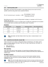
Page 37: ...n diode and the PSD4xx will be defective Please refer to the following table to find the maximum permissible speed Device type PSD401 PSD411 5V PSD401 PSD411 8H 14H PSD403 PSD413 8H 14H PSD422 PSD432...

Page 38: ...Notes 7100 006424_Bus description_PSD4xx_CA_H_ENG 38 08 04 2020 6 Notes...

Page 39: ...Tel 49 7661 39 63 0 info halstrup walcher com www halstrup walcher com halstrup walcher GmbH Stegener Stra e 10 79199 Kirchzarten...

Reviews: