background image

Digital Pulsed Input ( DPI )

Digital Pulsed Inputs are capable of accepting pulsed input information such as for a 
road speed sensor. These inputs measure the time periods between the pulses and
can process this information to provide quantities such as road speed. 
One


additional input can be connected using the Optional Rear Auxiliary 

Harness ( HT040003 ) 

Digital Pulsed Outputs ( DPO ) 

Digital Pulsed Outputs are capable of producing pulsed waveforms with varying duty 
and frequency. DPO's can be used to control various devices such as thermo-fans, 
shift lights, bypass air control valves, boost control solenoids etc. 
When a Digital Pulsed output is activated by the ECU the output will switch to ground. 
Solenoid valves and shift lights etc can be run directly from the output, however 
high current devices such as thermo-fans and additional fuel pumps must be activated 
through a relay. This way the DPO is only switching a relay and not a high current 
draw device.
Two additional outputs can be connected using the Optional Rear Auxiliary 
Harness ( HT040003 ) 

Digital Pulsed Outputs are limited to 800mA Max current draw.

Digital Switched Outputs ( DSO )

Digital Switched Outputs are capable of switching to ground
DSO's can be used to control relays in an on / off state only.
Two additional outputs can be connected using the Optional Rear Auxiliary 
Harness ( HT040003 )

Digital Switched Outputs are limited to 800mA Max current draw.

Analogue Voltage Inputs ( AVI )

Analogue Voltage Inputs accept variable voltage inputs from 0V to 5V. These inputs
can also accept switch inputs that change between two different voltage levels. 
The On Voltage and Off Voltage define what the thresholds are between the On and Off
states. The Voltage can be viewed as a channel in the software to determine the 
thresholds for a switched input.
Two additional sensors or switched inputs can be connected using the 
Optional Rear Auxiliary Harness ( HT040003 ) 

Wire connections


When using crimp connectors ensure that the correct crimping tool is used – if in
doubt do a pull test on a crimp connector, the wire should break before the wire
pulls out of the crimp. Terminal soldering can weaken a connection and should only
be used as a last resort. If solder joints are used, ensure joints are well isolated
from movement as solder joints are prone to fracture.
When splicing 2 wires it is preferable to use a crimp splice – again if using a solder
joint, ensure joint is limited in its range of possible movement as solder joints are
prone to fracture. Always use heat-shrink sleeving to insulate wires.


6.

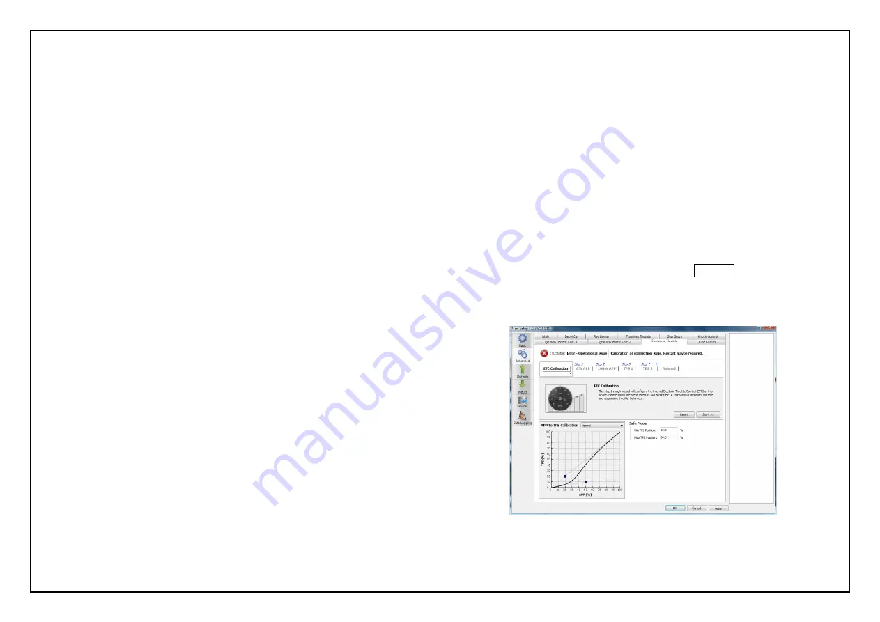
Calibration of the Electronic Throttle

Before trying to start the vehicle the Electronic throttle 

MUST 

be calibrated.

Calibration of the throttle is achieved by using the Haltech ECU Manager ETC 
Calibration wizard located in the Advanced Tab within the Main setup page.
The process to Calibrate the Electronic Throttle is outlined below.

Install ECU into vehicle as described previously

With the ignition switch turned on, connect to the ECU via 
Haltech ECU Manager Software using the USB cable provided

Navigate to the Main Setup page by pressing F4 or by using the 
Setup / Main Setup Tabs 

Go to the Advanced setup page via selecting the icon on the left of the 
main setup page

Select Electronic Throttle Tab to display the Haltech Electronic Throttle 
Calibration wizard, we are now ready to calibrate the throttle. 
To begin the calibration process select the   Start >>   button

The Haltech Calibration wizard will now guide you though the Electronic 

              Throttle Calibration.

Figure 7- Main Setup Page showing Advanced Menu ETC Calibration Wizard

Summary of Contents for Platinum Pro Plug-in

Page 1: ... FAX 612 9729 0900 EMAIL sales haltech com HALTECH US OFFICE EMAIL usa haltech com See the Haltech Website for your local authorized dealer www haltech com Version 4 PLATINUM PRO PLUG IN Hyundai Genesis BK Theta HT055045 QUICK START GUIDE ...

Page 2: ...ified vehicles listed but variations in wiring and connections on vehicles can occur and therefore this should be checked BEFORE the unit is installed Haltech highly recommends installation and tuning of this product is to be carried out by a professional with an understanding on installing and tuning engine management systems Misuse of this product can destroy your engine WARNING This ECU is desi...

Page 3: ...fer to before completing your installation and configuration The Manual can also be downloaded from the Haltech website www haltech com Supported Vehicles The Platinum Pro Plug in Hyundai Genesis BK Theta ECU supports the following Hyundai Genesis USA Only 2 0L turbo Theta engine Key start and Push button Start manual only Platinum Pro Plugin Hyundai Genesis BK Theta Kit Includes Haltech Platinum ...

Page 4: ...ill be located in the engine bay near the firewall on the drivers side Figure 1 ECU Location in engine bay 2 With the ignition turned off remove the ECU connector from the ECU by lifting the connector levers up and pulling the connectors out With the connector disconnected remove the Factory ECU from the engine bay by loosening the 4 x 10mm bolts securing it to the mounting bracket Figure 2 Factor...

Page 5: ...Theta 3 Using the Haltech mounting kit provided mount the Platinum Pro Plug in ECU to the mounting bracket with the 4x captive nuts and screws as shown below Figure 3 Mounting bracket captive nut attachment and assembly Figure 4 Platinum Pro Plug in ECU mounted on Haltech mounting bracket ...

Page 6: ...r Expansion is made possible by the addition of multiple expansion devices that communicate to the main ECU via a Control Area Network CAN Installation time and costs are kept to a minimum as all expansion devices are powered up from the main ECU via the pre terminated connection cable that comes with each expansion device Simply connect the device directly to the 8 pin CAN connector on the rear o...

Page 7: ...tates The Voltage can be viewed as a channel in the software to determine the thresholds for a switched input Two additional sensors or switched inputs can be connected using the Optional Rear Auxiliary Harness HT040003 Wire connections When using crimp connectors ensure that the correct crimping tool is used if in doubt do a pull test on a crimp connector the wire should break before the wire pul...

Page 8: ...sed Input DPI 2 Additional Digital Pulsed Outputs DPO 2 Additional Digital Switched Outputs DSO 4 Additional Analogue Voltage Inputs AVI These extra Inputs Outputs can be used to Fit additional sensors eg MAP Temperature and Flex Fuel Control additional devices via relays Control additional solenoids directly eg Aftermarket Boost Control solenoid The Rear Auxiliary harness is available as an optio...

Page 9: ...quivalent settings are available However new settings not in the original map will be substituted with values from the new version s default map Whenever ECU Manager converts your ECU map you should always check your map settings to ensure that all the appropriate settings have been converted correctly Step 3 Throttle Position Sensor 1 TPS 1 Release the accelerator pedal to a non pressed state Ens...

Page 10: ...is performed similar to any other Windows software package Installation is outlined below to ensure correct installation 1 Insert the CD ROM into your PC s CD ROM drive The CD should automatically launch into the Haltech Browser If the CD does not run automatically double click on the My Computer icon on the desktop double click on the Haltech icon CD ROM drive to start the browser software 2 The ...

Page 11: ...is performed similar to any other Windows software package Installation is outlined below to ensure correct installation 1 Insert the CD ROM into your PC s CD ROM drive The CD should automatically launch into the Haltech Browser If the CD does not run automatically double click on the My Computer icon on the desktop double click on the Haltech icon CD ROM drive to start the browser software 2 The ...

Page 12: ...quivalent settings are available However new settings not in the original map will be substituted with values from the new version s default map Whenever ECU Manager converts your ECU map you should always check your map settings to ensure that all the appropriate settings have been converted correctly Step 3 Throttle Position Sensor 1 TPS 1 Release the accelerator pedal to a non pressed state Ens...

Page 13: ...sed Input DPI 2 Additional Digital Pulsed Outputs DPO 2 Additional Digital Switched Outputs DSO 4 Additional Analogue Voltage Inputs AVI These extra Inputs Outputs can be used to Fit additional sensors eg MAP Temperature and Flex Fuel Control additional devices via relays Control additional solenoids directly eg Aftermarket Boost Control solenoid The Rear Auxiliary harness is available as an optio...

Page 14: ...tates The Voltage can be viewed as a channel in the software to determine the thresholds for a switched input Two additional sensors or switched inputs can be connected using the Optional Rear Auxiliary Harness HT040003 Wire connections When using crimp connectors ensure that the correct crimping tool is used if in doubt do a pull test on a crimp connector the wire should break before the wire pul...

Page 15: ...r Expansion is made possible by the addition of multiple expansion devices that communicate to the main ECU via a Control Area Network CAN Installation time and costs are kept to a minimum as all expansion devices are powered up from the main ECU via the pre terminated connection cable that comes with each expansion device Simply connect the device directly to the 8 pin CAN connector on the rear o...

Page 16: ...Theta 3 Using the Haltech mounting kit provided mount the Platinum Pro Plug in ECU to the mounting bracket with the 4x captive nuts and screws as shown below Figure 3 Mounting bracket captive nut attachment and assembly Figure 4 Platinum Pro Plug in ECU mounted on Haltech mounting bracket ...

Page 17: ...ill be located in the engine bay near the firewall on the drivers side Figure 1 ECU Location in engine bay 2 With the ignition turned off remove the ECU connector from the ECU by lifting the connector levers up and pulling the connectors out With the connector disconnected remove the Factory ECU from the engine bay by loosening the 4 x 10mm bolts securing it to the mounting bracket Figure 2 Factor...

Page 18: ...fer to before completing your installation and configuration The Manual can also be downloaded from the Haltech website www haltech com Supported Vehicles The Platinum Pro Plug in Hyundai Genesis BK Theta ECU supports the following Hyundai Genesis USA Only 2 0L turbo Theta engine Key start and Push button Start manual only Platinum Pro Plugin Hyundai Genesis BK Theta Kit Includes Haltech Platinum ...

Page 19: ...ified vehicles listed but variations in wiring and connections on vehicles can occur and therefore this should be checked BEFORE the unit is installed Haltech highly recommends installation and tuning of this product is to be carried out by a professional with an understanding on installing and tuning engine management systems Misuse of this product can destroy your engine WARNING This ECU is desi...

Page 20: ... FAX 612 9729 0900 EMAIL sales haltech com HALTECH US OFFICE EMAIL usa haltech com See the Haltech Website for your local authorized dealer www haltech com Version 4 PLATINUM PRO PLUG IN Hyundai Genesis BK Theta HT055045 QUICK START GUIDE ...

Reviews: