background image

5

ECOVENT Operating Instructions

ECO

V/1

120

12/re

v1/EN

Section 1 – Installation


Instructions:   

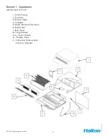
1.3.1. Place the door magnet (11) as Fig 1. and mark the fitting


hole on top of the oven door.


1.3.2. Drill on No. 2.4mm diameter hole, and tap with M3 thread.


1.3.3. Fix the magnet into place, ensuring the distance is set to read,


when door is opened to ventilation position.


Information:   

The reed switch is already fixed to the condensate hood.

1.4 Connection to Services


Information:   

The condensate hood requires a cold water supply, a suitable


waste pipe fitted to the drain and a 120 volt single phase

    electrical 

supply.


Instruction:    

1.4.1 Cold Water Supply. Fit the ¾” nylon Y branch (9) to the


inlet connection on the underside of the oven. Onto this flexible


hose (10) is to be fitted, with the opposite end connecting to the


inlet on the rear of the condensate hood. Check your Electrolux


manual for correct water quality etc.


1.4.2. Drain Connection. The drain pipe has been designed to


allow ease of interface with a 1 ¼” waste pipe. The smaller pipe


is an overflow, and should not be connected to the waste.


1.4.3. Electrical Supply. Remove the back plate (7) to allow access


to controls compartment. Connect a 120v/1/60 supply into the


designated connector block. Refit to panel.


Information:   

For further information see wiring diagram in section 3.2

Summary of Contents for ECOV-10

Page 1: ...ECOVENT Condensate Hoods Model ECOV 10 ECOV 20 ECOV 30 ECOV 40 ECOVENT Condensate Hoods Operators Instructions...

Page 2: ...to Oven 4 1 3 Fitting Door Magnet 4 1 4 Connection to Services 5 1 5 Commissioning 6 Section 2 Operation 2 1 Safety 7 2 2 Regular Operation 7 2 3 Cleaning and Maintenance 8 Section 3 Technical and Pe...

Page 3: ...N Section 1 Installation Identification of Parts 1 Outer Casing 2 Top Shell 3 Bottom Shell 4 Cassette 5 Mesh Moisture Eliminator 6 Baffle Filter 7 Back Plate 8 Fixing Bracket 9 Nylon Branch 10 Flexibl...

Page 4: ...e roof panel in place Screw the fixing bracket 8 into position using the holes provided 1 2 2 Remove the nuts from the two locating studs fitted to the bottom rear of the condensate hood Safety 1 2 3...

Page 5: ...d a 120 volt single phase electrical supply Instruction 1 4 1 Cold Water Supply Fit the nylon Y branch 9 to the inlet connection on the underside of the oven Onto this flexible hose 10 is to be fitted...

Page 6: ...ds factory setting before returning to idle Closing the door will also return the condensate hood to idle Instruction 1 5 2 Prior to running the condensate hood for the first time ensure that both the...

Page 7: ...part of a condensate hood presents itself as a possible fire hazard Ensure baffle filters are cleaned regularly and while they are removed clean internal areas that are accessible 2 1 8 Damage due to...

Page 8: ...ce suggests 2 3 6 The cold water mist nozzles should be checked for operating and the apertures cleaned with fine wire when required 2 3 7 To remove baffle filters lift and swing bottom away from you...

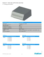
Page 9: ...CFM Cold Water Supply Always 40PSI Weigth ECOV 10 lbs ECOV 20 lbs ECOV 30 lbs ECOV 40 lbs Construction Material 18 ga stainless steel ECOV 10 Electrolux Oven air o convect 62 102 Model PNC 269281 PNC...

Page 10: ...holidays Travel time service charges miscellaneous tools material charges and labor charges resulting from inaccessibility of equipment will not be paid by Manufacturer This LIMITED WARRANTY SHALL AP...

Reviews: