Operators Manual
Operation, Maintenance and Service
Capture Jet
®
Hoods with Water Wash
Model: KVE-WW, KVC-WW
Page 1: ...Operators Manual Operation Maintenance and Service Capture Jet Hoods with Water Wash Model KVE WW KVC WW...
Page 2: ...a claim if needed GENERAL INSTALLATION It is the responsibility of the installing contractor to see that the system installation is completed in accordance with the project plans and specifications an...
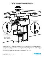
Page 3: ...ng the rods to the hood through the hanger brackets that are welded to the top of the hood Use of turnbuckles will make final adjustment easier Standard hanging height for canopy hoods ranges from 78...
Page 4: ...unted inside or on top of the hood or mounted in an electrical enclosure Information regarding the fan and speed controller see pg 12 2 Each Halton Capture Jet hood system will have a KSA filter remov...
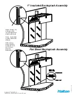
Page 5: ...v1 EN Screw through top of flange to wall screw head will not interfere with hood Screw backsplash to wall or attach with adhesive Halton canopy hoods should be installed from 78 min 84 max above the...
Page 6: ...ed to the top of the hood using the turnbuckles will make final adjustments easier Hanging height of Canopy hoods should be per local building codes verify with Authority Having Jurisdiction for hangi...
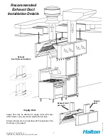
Page 7: ...Duct may be attached to supply collar with sheet metal screws or pop rivets and sealed with duct tape Screws or Rivets are not to interfere with the operation of the fire damper if equipped Recommend...
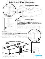
Page 8: ...g together or as an option using screws for models with supply plenum U Channel For hood models that are placed back to back as shown in Fig 1 Slide the U Channel A up over the back of the hood system...
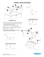
Page 9: ...rtical flange at the bottom of closure panel and vertical flange on top of hood should line up 2 Hammer clips C over the two vertical flanges 3 Attach panels B to wall using appropriate hardware D 4 S...
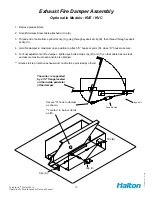
Page 10: ...er in maximum open position to attach S hooks at point D close S hooks to secure 5 For final adjustment of fire damper tighten eye bolts at clips A B and C so that cable has no slack and assure maximu...
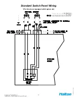
Page 11: ...Jet Water Wash Operation Maintenance Service Manual CJOWWM 012009 rev1 EN Standard Switch Panel Wiring For Hoods not equipped with Capture Jet By Electrician By Halton Wires Numbered as shown in junc...
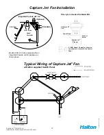
Page 12: ...A Filter Integrated Capture Jet fan Standard Optional Speed Controller 5 AMP Speed Controller wired on top of hood or located in the Control Panel Capture Jet Plenum Capture Jet Fan This style is stan...
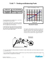
Page 13: ...e corresponding pressure is read off the chart as 0 19 inches of Water Column Capture Jet T A B Port Readings Hood Model Design T A B inches WC KVE KVC 0 20 T A B Testing and Balancing Ports The Captu...
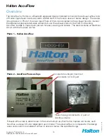
Page 14: ...re between ambient air and the exhaust plenum the T A B Port reading AccuFlow installs in Capture Jet plenum for easy viewing and access The device shares an electrical circuit with the Capture Jet fa...
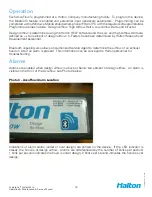
Page 15: ...sign airflow K Factors have been determined by Halton Research and Development personnel Bluetooth capability also allows an Authorized Service Agent to determine the airflow of an exhaust hood on sit...
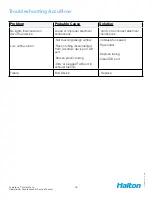
Page 16: ...on AccuFlow device Loose or improper electrical connections Verify or reconnect electrical connections Low airflow alarm Not reaching design airflow Plastic tubing disconnected from Accuflow device o...
Page 17: ...A filter slots and lift upward until filter slides out of plenum To install filter Place filter on KFR filter removal tool bracket raise filter into place inside exhaust plenum Slide upward until top...
Page 18: ...uorescent lighting available KSA Filters 78 84 A F F Standard Verify with Authority in project location for min hanging height 16 ga duct work all welded per code Standard Capture Jet intake location...
Page 19: ...2009 rev1 EN Model KVC WW Typical Installation Filtered MUA unit on the roof 40 min 120 min 16 ga duct work all welded per code Stainless Steel KSA filters Capture Jet air 78 84 A F F 78 Std Make up a...
Page 20: ...hoods but it can drive multiple fans if required Controls exhaust fan and make up air fan Controls cold water hot water Either local or remote AUTO WASH RUN operation mater slave configuration for mul...
Page 21: ...the hole for field termperature and pressure reading Cold Water and Hot Water Strainers The strainers located in the PRV valve are used to strain out dirt from the water flow and to protect the solen...
Page 22: ...e panel it indicates then there is a problem To silence the alarm press the MUTE button however the indicator lamps will remain lit DISPLAY CAUSE SOLUTION Low Level Detergent Low level of detergent in...
Page 23: ...ins active even when unit is in Off position Remote AUTO WASH RUN switch Used to remotely turn the system in RUN and WASH If remote control for the panel is needed this switch is on AUTO position This...
Page 24: ...in the system TD 200 Siemens display text display shows text messages displayed in two rows system status Soft touch buttons on the display square shape located bellow messaging display Wash time butt...
Page 25: ...position turn off sequence is as follows The unit displays WASH ON 60 SEC DELAY Exhaust fan is off Make up air fan is off Washing cycle is delayed for 60 seconds allowance for fan to stop Automaticall...
Page 26: ...electronic text display Currently set value in minutes is displayed 2 Press the ENTER button a blinking cursor appears 3 Use the up and down arrows to set desired wash time 4 Press ENTER again to fini...
Page 27: ...27 Capture Jet Water Wash Operation Maintenance Service Manual CJOWWM 012009 rev1 EN FIELD WIRING DIAGRAM...
Page 28: ...WIRING DIAGRAM 1M 0 0 0 1 0 2 0 3 0 4 0 5 0 6 0 7 2M 1 0 1 1 1 2 1 3 1 4 1 5 M L SIEMENS S7 200 0 6 0 0 1L 0 1 2L 0 3 0 2 0 4 0 5 3L 0 7 1 0 1 1 L1AC N EXHAUST FAN RUN WASH G N L N H W SOL DETERGENT...
Page 29: ...TROUBLE SHOOTING GUIDE INOPERATIVE PROBLEM CAUSE SOLUTION Exhaust fan will not function Field Wiring Breaker or Burned Contactor Verify field wiring for proper connections Check fuse at control panel...
Page 30: ...e charges miscellaneous tools material charges and labor charges resulting from inaccessibility of equipment will not be paid by Manufacturer This LIMITED WARRANTY SHALL APPLY ONLY to products that ha...