4
Capture Jet
®
Water Wash
Operation & Maintenance & Service Manual
CJ
O
WWM/0
120
09/re
v1/EN
OPERATION OF SYSTEM
1. After installation is complete, it will be necessary to check and balance the airflows. On the Capture Jet
®
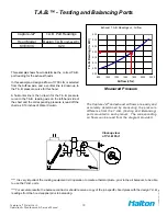
line of hoods, Halton supplies T.A.B. (testing and balancing) ports for measuring the pressure drop. These
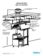
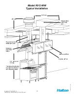
ports are located on the inside of the canopy on each plenum. (
Exhaust and Capture Jet
®
).
For details on their use
(
see pg. 13
)
. For hoods without ports, use of standard practices (duct traverse /
average velocity / etc) for measuring airflows will be required.
**It is very important that the fan for the Capture Jet
®
air be balanced according to specifications.
See the job specific information for required airflows. Adjustments to the Capture Jet
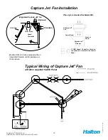
®
fan can be made
with the speed controller supplied with the fan. This speed controller will be mounted inside or on top of the
hood, or mounted in an electrical enclosure.
Information regarding the fan and speed controller (see pg. 12).
2. Each Halton Capture Jet
®
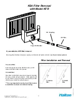
hood system will have a “KSA” filter remover
(model KFR).
The “KFR” will be
packaged separately, inside the hood, the box will be labeled “Attn: Kitchen Mgr. “ Model KFR instructions on
(pg. 14).
The KFR will assist in removal of the filters for assembly and cleaning.
3. After the exhaust and supply airflows have been properly balanced, a final inspection should be made to
ensure proper system operation.
HOOD MAINTENANCE
1.
Clean the hood canopy inside and out as needed with mild soap and water. Never use harsh or abrasive
cleaners on Stainless Steel or Painted surfaces, making sure to wipe clean all interior and exterior
surfaces of the hood including the light fixtures.
** Never clean the hood canopy when any of the surfaces are hot.
2. Clean the filters and grease cup(s) daily, first washing by hand, and then placing them into a dishwasher or
by steam cleaning.
** Handle the Grease filters carefully **

