18
MM1 Series Hood Installation, Operation & Maintenance Manual
OM032/0920
18/re
v6/EN
duct is included to make the connection to the exhaust ductwork. The exhaust collar and
the transition have 1” flanges to facilitate connection to the exhaust ductwork. All duct
connections must be 100% liquid tight welded per NFPA 96 requirements.
The MM1 hood may also be connected to Metal Fab pre-engineered exhaust ducting. The hood
would then be ordered with a 14” diameter round exhaust collar attached to the hood and comes
with a 14” diameter by 9” tall round extension for the duct (Metal Fab part no. 14PSW9) and duct
connector (Metal Fab part no. 14RHC, called a flange band in the following instructions) and a
tube of caulk (P080 sealant) which is used in the assembly of the duct sections. Appendix 2 is
an instruction sheet from Metal Fab which describes the assembly of the duct sections. These
instructions must be followed carefully and completely.
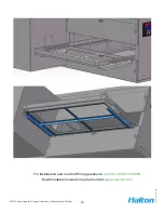
7. Replace fascia panels if they have been removed.
8. Complete Ansul installation (page 26, Fire Suppression System) if required.
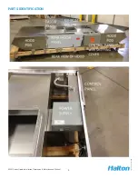
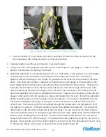
A. Locate the hood control panel and remove and discard the shipping cover (keep the
screws) and remove the control panel face plate. The control panel is located at the rear
of the hood assembly, recessed into the rear fascia panel between the hood pods, see
photo below.
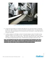
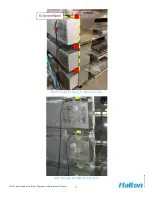
B. Field wire terminals F9A and F10 to an open set (when Ansul fire suppression system
is cocked) of dry contacts on one of the Ansul system micro switches. The Ansul micro
switches are found in the Ansul Automan Regulated Release assembly.
The contacts will close when the system discharges. This will send a signal to the control
panel that the fire suppression system has actuated. Fire suppression systems may not
be required in some jurisdictions. Skip this step if no fire suppression system for the
ovens is in place.
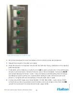
Control Panel Locations
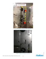
Wiring harness and Current switches shipped
Inside Control Panel

