2
MM1 Series Hood Installation, Operation & Maintenance Manual
OM032/0920
18/re
v6/EN
GENERAL DESCRIPTION
Halton’s MM1 Series hood is designed to efficiently capture and remove the grease, smoke, and
other effluents generated when cooking with pizza ovens. The hood is designed to mount close to
the top of the pizza oven which provides an operational advantage of capturing the grease, smoke
and other effluents directly above the pizza oven outlets. By localizing the capture area the hood can
efficiently capture and effectively eliminate convective heat spillage to the store.
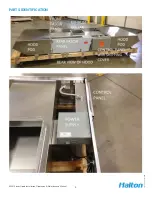
The MM1 has a control panel that is designed to set the exhaust airflow based on the number of
oven decks in operation to maximize energy savings potential. Exhaust airflow is monitored at all
times via a T.A.B. (Test And Balance) Port installed in the hood plenum. A wiring harness connects
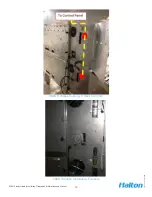
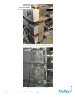
between the pizza oven’s blower motor control boxes and exhaust hood’s control panel to report
when the oven is on and how many oven decks are operating. Additionally, makeup air operation (on/
off) is dictated by the control panel to maintain kitchen space air balance. An oven wiring harnesses
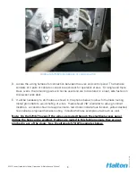
and current switches to monitor the pizza ovens are included and are shipped inside the control panel
for field installation. The control panel contains a terminal strip for field connection to the exhaust
fan, the fire suppression system (if required) and the make up air fan (if used). All wiring must
conform to local electrical and building codes. Field wiring instructions begin on page 18.
The exhaust hood’s control panel is recessed into the rear fascia panel of the hood, with status
lights on the control panel face for troubleshooting purposes. The indicator lights show status for
each oven deck, status of the exhaust fan and the makeup air unit. A manual override switch to drive
the hood to full design airflow is incorporated as well. This switch should only be used if a problem
occurs with the hoods control panel sensing the pizza oven’s individual decks on/off status. Field
wiring of the control panel interface with the pizza oven decks, using the oven wiring harness, should
be performed before the oven/hood is placed in its final position, especially if the oven is to be
positioned near a wall. Access to the pizza oven’s blower motor control box for each deck is required
to complete the oven wiring harness installation process.
Make up air, if used, should operate any time the exhaust fan for the pizza hood is on to assure the
proper air balance in the kitchen. The only exception to this is during a fire event in the pizza oven. In
this case the exhaust fan will remain on and the make up air will shut off.
Part of the Control Panel wiring is a provision to detect a dry contact (micro switch) closure in the
fire suppression system when the fire suppression system activates. Two wires from the terminal
strip contacts numbered 9A and 10 must be connected between the fire suppression system and the
control panel for correct exhaust fan operation in the event of a fire event. Local fire codes typically
require the exhaust fan to turn on during a fire event. See detailed field wiring instructions starting
on page 18.
Oven power (natural gas and electric) must be tied into the fire suppression dry contacts (micro
switches) to ensure shutdown of cooking equipment in case of a fire. For electrical control, this
is typically achieved by tying the oven power inlet to a shunt trip breaker connected to the fire
suppression dry contacts. For natural gas supply, an electronically actuated solenoid valve is tied to
the fire suppression dry contacts.
The control panel is only to be used with an EC (electronically commutated) equipped exhaust fan.
Optional low voltage transformer must be factory installed when selecting the exhaust fan.
For Installation and Control Wiring questions:
call EVS at 586-779-0996.


