background image

31

MM1 Series Hood Installation, Operation & Maintenance Manual  

OM032/0920

18/re

v6/EN

AIR BALANCE

1.  After installation is complete, it will be necessary to check and balance the airflows for the 

building.

a.  Note:  Adjustments to the exhaust fan should not be made without consulting 

EVS.  The control system varies the exhaust flow based on the number of decks in 
operation as determined by inputs from the oven wiring harness and T.A.B. Port. 

2.  To ensure proper hood performance, locate all makeup and supply air diffusers a minimum of 2 

feet away from the exhaust hood perimeter. 

3.  To ensure that proper air balance is maintained, the makeup air unit shall be interlocked with 

the exhaust fan operation.

a.  Note:  When a fire suppression system is installed, the makeup air unit is configured 

to be OFF in the event of a fire while the exhaust fan is to run at full design airflow. 

4.  After the system has been placed into service and the balancing of airflows has been 

accomplished, a final inspection should be made.  Check for unusual noises, excess exhaust or 
supply rates and general operation of the system.

HOOD MAINTENANCE 

1.  Clean the hood pods inside and out as needed with mild soap and water.  Never use harsh or 

abrasive cleaners on Stainless Steel or Painted surfaces. 

2.  Clean the hoods’ grease filters and grease cups daily, first washing by hand, and then placing 

them into a dishwasher for cleaning or by steam cleaning them.

Please Note:  Handle the Grease filters carefully 

Standard Equipment

•  4 Aluminum Filters
•  Exhaust Hood is Listed per UL710
•  Exposed Surfaces are 430 Stainless Steel

Optional Equipment

•  Side Skirts (Painted is Optional)
•  Front Eyebrow Section 
•  Cool Front Modified End Panels

Summary of Contents for MM1 Series

Page 1: ...MM1 Series Hoods Model MM1 Form OM032_MM1_Series_Hoods Date 09 2018 Rev6 Operators Manual for MM1 Series Hood Manual provides Operation Maintenance and Service Instructions...

Page 2: ...ve the hood to full design airflow is incorporated as well This switch should only be used if a problem occurs with the hoods control panel sensing the pizza oven s individual decks on off status Fiel...

Page 3: ...ovens both gas and electric The hood can be used with single double or triple stack configurations at the design exhaust airflows shown on the submittal drawings in Appendix 1 Optional side skirts Mo...

Page 4: ...4 MM1 Series Hood Installation Operation Maintenance Manual OM032 092018 rev6 EN PARTS IDENTIFICATION...

Page 5: ...5 MM1 Series Hood Installation Operation Maintenance Manual OM032 092018 rev6 EN ITEMS SHIPPED INSIDE CONTROL PANEL...

Page 6: ...ll thread rods at the hood For structural calculations assume the hood assembly weighs 500 lbs The fascia panels between the pods are removable to facilitate assembly Removing the front panel will all...

Page 7: ...nd oven B Locate the control panel at the exhaust hood and wiring diagram for the system Review the wiring diagram and all instructions prior to beginning the process C Install current switches on blo...

Page 8: ...ries Hood Installation Operation Maintenance Manual OM032 092018 rev6 EN Installation of Current Switch on 570 670 Alternate Installation of Current Switch on 570 670 wires routed into electrical acce...

Page 9: ...owest oven deck E It will be necessary to drill holes as shown in the photos below to allow for harness routing Install grommets to avoid chafing of wires Holes should 7 8 diameter to allow grommet in...

Page 10: ...10 MM1 Series Hood Installation Operation Maintenance Manual OM032 092018 rev6 EN 360G Harness Routing 2 Deck Example 360G Harness Installation Example...

Page 11: ...11 MM1 Series Hood Installation Operation Maintenance Manual OM032 092018 rev6 EN 670 Harness Routing 3 Deck Example 670 Harness Installation Example...

Page 12: ...to thermostat line Alternate 570 670 Install Example Avoid attaching adhesive pads directly to areas that get hot during cooking F The 8 pin connector should be positioned near the control panel loca...

Page 13: ...e labeled to indicate appropriate oven deck Locate Deck 1 2 pin connection and connect to the current switch Ensure the all wires are safely installed using fastener mount cable holders and zip ties a...

Page 14: ...the hood Tabs are provided along the side skirt flange which runs down the oven body which allows the side skirt to be attached to the oven at predetermined points These points are places where the e...

Page 15: ...15 MM1 Series Hood Installation Operation Maintenance Manual OM032 092018 rev6 EN Side Skirt Attachment Side Skirt Knobs Side Skirt Attachment Side Skirt Attachment...

Page 16: ...16 MM1 Series Hood Installation Operation Maintenance Manual OM032 092018 rev6 EN...

Page 17: ...compliant ductwork The hood is fabricated with a 14 X 14 exhaust collar When the hood is used with a triple stack oven the exhaust duct should be 14 X 14 to the exhaust fan When the hood is used with...

Page 18: ...tions These instructions must be followed carefully and completely 7 Replace fascia panels if they have been removed 8 Complete Ansul installation page 26 Fire Suppression System if required A Locate...

Page 19: ...upon makeup air unit configuration Please refer to site drawings to determine if required The field wiring from Terminal Strip contacts M98 and M99 to the make up air start stop contactor shall be 2...

Page 20: ...20 MM1 Series Hood Installation Operation Maintenance Manual OM032 092018 rev6 EN RTC Solutions FSC Speed Controller...

Page 21: ...21 MM1 Series Hood Installation Operation Maintenance Manual OM032 092018 rev6 EN Exhaust Fan Control Greenheck Fan Controller...

Page 22: ...22 MM1 Series Hood Installation Operation Maintenance Manual OM032 092018 rev6 EN Wiring for S P fan with PerfectSpeed Controller PerfectSpeed Controller on Fan PerfectSpeed Controller Wiring...

Page 23: ...g power source Connect a three wire 120V 15A circuit to terminals L Line N Neutral and G Ground in the Power Supply Box 10 Commission system starting on page 29 Make sure grease filters and grease cup...

Page 24: ...r to be removed and installed from the end of the conveyor if the side skirts are installed Remove the crumb tray from its bracket Each bracket consists of two pieces that are assembled into the exist...

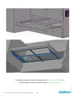
Page 25: ...MM1 Series Hood Installation Operation Maintenance Manual OM032 092018 rev6 EN For Installation and Control Wiring questions call EVS at 586 779 0996 Downloadable manuals may be found at www evsvent c...

Page 26: ...n is required the local Ansul installer must also design and install the distribution piping and nozzles for this requirement This work must be performed by the Ansul system installer The side skirts...

Page 27: ...27 MM1 Series Hood Installation Operation Maintenance Manual OM032 092018 rev6 EN MM1 Typical Fire Suppression System Isometric View...

Page 28: ...28 MM1 Series Hood Installation Operation Maintenance Manual OM032 092018 rev6 EN MM1 Typical Fire Suppression System Schematic...

Page 29: ...o off and exhaust fan will go to full speed 3 When the manual override is activated the exhaust fan will operate at full speed Commissioning 1 Ensure that the oven wiring harness is installed all fiel...

Page 30: ...panel circuitry must be removed Remove the front cover of the control panel Remove the BLUE wire jumper between terminals 1 and 2 This will initiate an override setting that will change the default e...

Page 31: ...led the makeup air unit is configured to be OFF in the event of a fire while the exhaust fan is to run at full design airflow 4 After the system has been placed into service and the balancing of airfl...

Page 32: ...lton Part Number Filter 12 x 16 Aluminum Baffle 10163 Filter 12 x 20 Aluminum Baffle 10164 14 x 14 to 11 5 x 11 5 transition 57443 9 Duct Collar Extension 14PSW9 3AO Round Duct 11461 Collar Connector...

Page 33: ...33 MM1 Series Hood Installation Operation Maintenance Manual OM032 092018 rev6 EN Wiring Diagram Detail Oven Wiring Harness 8 Pin Connector...

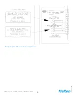
Page 34: ...34 MM1 Series Hood Installation Operation Maintenance Manual OM032 092018 rev6 EN Wiring Diagram Detail Field wiring close up Airflow Jumper Detail Wiring close up...

Page 35: ...35 MM1 Series Hood Installation Operation Maintenance Manual OM032 092018 rev6 EN Wiring Diagram Detail Jumper wiring close up...

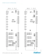
Page 36: ...36 MM1 Series Hood Installation Operation Maintenance Manual OM032 092018 rev6 EN Jumper Positions on MC8 Controller...

Page 37: ...43 MM1 Series Hood Installation Operation Maintenance Manual OM032 092018 rev6 EN Appendix 2 Pre Fab Duct Installation...

Page 38: ...ons and that it meets all specific requirements of lo cal code officials The local authority having jurisdiction could overrule some of the installation details written in this manual The installation...

Reviews: