6
MM1 Series Hood Installation, Operation & Maintenance Manual
OM032/0920
18/re
v6/EN
MODEL MM1 INSTALLATION INSTRUCTIONS
SUGGESTED SEQUENCE OF ASSEMBLE
1. Uncrate hood and side skirts (if side skirts were ordered). Inspect the crating carefully. If there
are signs of damage, call the freight carrier before uncrating the units. Uncrate the units carefully.
** Important note **
Do not leave units out in the weather for an extended time period. The protective PVC covering
around the hood will become very difficult to remove if left exposed to the weather conditions for
a long period of time.
The hood will be hung from the ceiling support structure using ½” all thread rods and ½ - 13
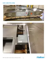
nuts. Use the hanging brackets that are attached to the back of each hood pod section, 4 places,
to anchor the all thread rods at the hood. For structural calculations assume the hood assembly
weighs 500 lbs. The fascia panels between the pods are removable to facilitate assembly.
Removing the front panel will allow easier access to the top of the hood and the ductwork
assembly.
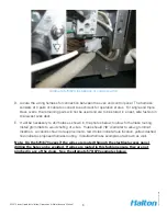
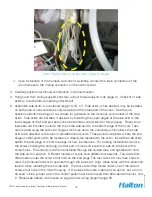
Additional parts are shipped inside the control panel. Remove the shipping cover that protects the
control panel face by removing the four screws that hold it in place. Save the four screws but the
shipping cover may be discarded. Remove the four additional screws that hold the control panel
face and inside you will find the oven wiring harness with an 8 pin connector on one end and
three 2 pin connectors on the other end, three current switches in boxes and a wiring diagram
in a packing list envelope. Do not lose these parts found inside the control panel; they are very
important to the operation of the MM1 hood. The control panel will be replaced using all 8
screws after all field wiring is completed.


