9
MM1 Series Hood Installation, Operation & Maintenance Manual
OM032/0920
18/re
v6/EN
Alternate 570/670 Installation of current switch
D. Locate the wiring harness for connection between the oven and control panel. The harness
consists of 3 pairs of cable to connect to each deck for operation status. For single and triple
stack ovens, the remaining pairs will not be used and are to be stored in a neat, safe fashion in
the lowest oven deck.
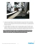
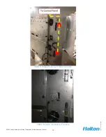
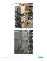
E. It will be necessary to drill holes as shown in the photos below to allow for harness routing.
Install grommets to avoid chafing of wires. Holes should 7/8” diameter to allow grommet
insertion. Locations shown are approximate - red circles indicate hole location, yellow dashed
line indicates proposed harness routing. Installed harness examples are shown as well.
Note: On the 570/670 ovens if the wires are routed through the electrical access panel
drilling the hole can be avoided. If wires are routed in this fashion ensure they are not
pinched in any of the doors. See the alternate 570/670 examples below.


