2
G
Operating instruction
Thank you for choosing a Hama product.
Take your time and read the following instructions and information completely. Please keep
these instructions in a safe place for future reference. If you sell the device, please pass
these operating instructions on to the new owner.
1. Explanation of warning symbols and notes
Warning
This symbol is used to indicate safety instructions or to draw your attention to specific
hazards and risks.
Note
This symbol is used to indicate additional information or important notes.
2. Package contents
• Monitor arm
• Mounting kit
• These operating instructions
Note
Please check the mounting kit for completeness before installing the product and ensure
that there are no faulty or damaged parts.
3. Safety instructions
Warning
•
Given the multitude of terminal devices available on the market, the supplied
mounting kit is unable to cover every option.
•
The screws for attaching the terminal device to the product may occasionally be too
long.
•
Read the operating instructions for your terminal device before attempting to mount
it. The instructions provide information about the type and measurements of suitable
fastening materials.
•
If the supplied mounting kit does not contain suitable fastening materials for
mounting the terminal device, purchase these from a specialised dealer.
•
Never apply force during assembly. This can damage your device or the product.
•
If in doubt, have this product mounted by a qualified technician - do not attempt to
mount it yourself!
Note - Commercial use
•
If the device is used commercially, increased duty of care requirements apply.
•
Therefore, please observe the accident prevention regulations of the German
employer’s liability insurance association for electrical systems and equipment.
Please also observe all accident prevention regulations from other applicable
employer’s liability insurance associations and accident insurance companies, as well
as any legal regulations applicable to the particular industry and/or location.
•
The bracket must be installed by trained personnel or by a special technician,
especially when installed in schools, educational institutions, hobby/self-service
workshops or other publicly accessible institutions.
•
Have trained personnel carry out regular inspections to ensure that the product is
securely installed, properly functioning and in acceptable condition (we recommend
inspections at least every 6 months, or more frequently if required for the particular
location) and then document these inspections.
•
Once you have mounted the product and the attached load, check that they are
sufficiently secure and safe to use.
•
You should repeat this check at regular intervals (at least every three months).
•
Ensure that the product does not exceed its maximum permitted carrying capacity and
that no load exceeding the maximum permitted dimensions is attached.
•
Make sure that the product is loaded symmetrically.
•
In the event of damage to the product, remove the attached load and stop using the
product.
•
Mount the product only on tabletops with a sufficient load-bearing capacity and stability
for the product and the device attached to it.
•
Ensure that the thickness of the tabletop is 1 - 8.5 cm.
•
Do not attach any additional objects to the product.
•
Keep the packaging material out of the reach of children due to the risk of suffocation.
•
Dispose of packaging material immediately in accordance with the locally applicable
regulations.
•
Note that the product can cause pressure marks on the surface of the table. This
depends on the weight loading and on the stability of the surface at the place of
installation.
4. Application and specifications
•
The product is intended only for use inside buildings.
•
Use the product only for the intended purpose.
Maximum load:
12kg
Screen diagonal:
33 – 89 cm (13"– 35")
Rotation:
180°
Tilt:
-/+ 45° (device-dependent)
Swivel range:
up to 180° on 3 joints (device-dependent)
Holder:
up to 100 x 100, according to VESA standards
5. Preparation and assembly
Note
•
The product must be mounted by two people. Seek assistance and help!
•
Different end devices have different connections for cabling and other devices.
Before commencing the installation, check whether the necessary connections can
still be reached after mounting.
•
Depending on the product and mounting method, you may not need all parts of the
mounting kit. It is therefore possible that unneeded screws and other small parts will
be left over even after correct mounting. Keep these in a safe place together with the
instructions for use for later reference (sale of the product, moving house).
•
Observe the other warnings and safety instructions.
•
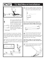
Proceed step-for-step in accordance with the illustrated installation instructions (Fig.
1a et seq.).
Note
•
Given the multitude of terminal devices structures available on the market, we cannot
describe all possible mounting options here.
•
Please ensure that the bracket lays flat and evenly on the back of the monitor.
•
Ensure that all screws have the proper length and can be mounted until they are
hand-tight (see Fig. 3).
6. Adjustment & maintenance
Note – Height adjustment
•
The bracket must be adjusted by two people! Seek assistance and help!
•
During adjustment, ensure that the product is loaded symmetrically and that the
maximum permitted carrying capacity is not exceeded.
Note – Setting/adjusting the tilt angle
•
To permanently set the tilt angle, loosen the fastening screws at the side, set the
desired tilt angle and then tighten the screws again (see Fig. 8).
•
In order to be able to flexibly adjust the tilt angle, turn the screws hand-tight only. In
this way, the screen can be adjusted at any time.
•
No screws need to be loosened for the sideways movement.
•
Please only swivel the monitor arm within the range indicated (Fig. 7)
Note
•
IN the case of a screen that is too light for the current setting, the supporting arm
will move upwards on its own. As a result, the spring strength must be reduced by
turning the setting screw in the (-) direction.
•
If the supporting arm moves downwards on its own, the spring strength must be
increase (+).
•
Always carry out any adjustment of the gas spring with the supporting arm fully
lowered!
•
To adjust the spring strength, turn the setting screw with the supporting arm fully
lowered using the Allen key (F) in the relevant marked direction (+) or (-) (Fig. 5).
•
After adjusting the spring strength, check whether the supporting arm along with the
attached weight sticks in various positions and does not move independently up or
down. Repeat the setting if necessary when the supporting arm is fully lowered.
•
Depending on the weight of the screen, multiple full revolutions of the adjusting screw
may be needed. Do not over-turn the setting screw, however (sudden difficulty moving)
•
Only clean this product with a slightly damp, lint-free cloth and do not use aggressive
cleaning agents.
7. Warranty disclaimer
Hama GmbH & Co KG assumes no liability and provides no warranty for damage resulting
from improper installation/mounting, improper use of the product or from failure to observe
the operating instructions and/or safety notes.


