11
g
Operating Instruction
Package contents:
1x ATA & eSATA RAID controller, PCIe
1x these printed installation instructions
1x driver CD-ROM
Controller specifi cations
• Supports PCIe specifi cation 1.0
• Supports serial ATA II hard drives with a max. transfer rate
of 3.0 Gbit/s on the eSATA ports
• Supports Native Command Queuing (NCQ) on the eSATA
ports
• Supports RAID functions 0, 1 or 0+1 and JBOD on the eSATA
and IDE ports
• Supports UDMA 6 = 133 Mbyte/s on the internal IDA / ATA
port
• Connections:
2x external eSATA ports according to SATA II specifi cation
1x internal IDA / ATA UDMA 133 port
Software support:
• Windows XP / XP x64-bit editions
• Windows Vista / Vista x64-bit editions
• Windows 7 / Windows 7 x64-bit editions
Hardware installation:
You must open your computer to install the card. Ensure that you
have fi rst disconnected your computer from the mains power.
If you are not familiar with the internal setup of your computer,
please consult your computer manual or ask a qualifi ed
technician.
• Switch off your computer and all connected devices.
• Unplug your PC before beginning installation.
• Open the cover (case) of your computer.
Note:
Be aware that static electricity can damage both the card
and your computer. Therefore, you should statically discharge
yourself by touching a metal object, for example a heating
radiator.
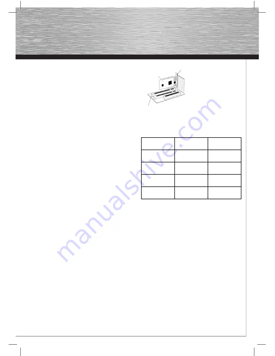
• Find a free PCIe slot. This card requires a PCIe slot of at
least size x1.
• Remove the slot cover for this slot.
• Hold the card by the edges of the circuit board and insert it
into the free PCIe slot.
• Carefully and gently press the card into the slot until the
holding bracket (card slot) is lined up with the case and the
gold-plated contacts have disappeared into the slot.
• Secure the card to the case using an appropriate screw.
• Connect your internal ATA/IDE devices (for example hard
drives or IDE CD-ROM drives) to the internal ATA/IDE port.
• Close the case of your computer and plug it back in to the
power
supply.
• If necessary, connect your external eSATA devices to the
controller.
• Switch your computer back on.
PCIe Slot
PCIe Card
Slot plate
Hardware Description:
Overview of the supported RAID versions:
Raid Level/
version
Type of hard
drive use
Number of hard
drives required
Raid 0-Stripe
Striping
(interconnection)
Min. 2, 3 or 4
Raid 1-Mirror
Mirroring
2
Raid 01-Stripe
+Mirror
Striping and
mirroring
4
JBOD-
Concatenate
Combining hard
drives
Min. 2, 3 or 4
BIOS confi guration:
The controller BIOS is displayed every time the computer
is booted up. The controller BIOS displays all hard drives or
CD/DVD drives that are connected. If a problem with a hard
drive or RAID array is indicated, have a look at the paragraph
titled
“Resolving RAID Confl icts”
or
“Replacing a Hard Drive
in an Existing RAID Array, RAID 1 or 0”
in these operating
instructions. You will fi nd further instructions about how to
proceed there.
RAID 0 interconnection (striping)
Note:
RAID level 0 requires at least two hard drives of the same data
capacity. Ideally, you should use two identical hard drives from
the same manufacturer. Some manufacturers offer special RAID
versions of their hard drives. We recommend that you use these
special hard drives, as these are specifi cally designed to meet
the requirements of RAID operation.
What is RAID level 0?
Put simply, RAID level 0 enables two or more identical hard
drives for simultaneous processing (reading and writing), which
means that the data throughput (speed) is considerably higher
than with one hard drive. In ideal conditions, this almost doubles
the data throughput rate.
g
Operating Instruction


