background image

17

LIGHTNING CURE LC8 シリーズにオプティカルフィードバックユニット(オプション)を取り付けることにより、オートモー
ド時に、光源の光フィードバック制御(絞りの自動開閉制御)が有効となります。

オプティカルフィードバックユニット(オプション)の調整

■  光量調整

q

  ランプを点灯させ、ランプ安定表示灯が点灯するまで待ちます。

w

  ライトガイドに光量計(UV メータ)を取り付け、測定可能な状態にします。

e

  プログラムモードで SHIFT ボタンと SELECT ボタンを押して光量設定表

示させ、SHUTTER の MANUAL ボタンを押してシャッターを開けます。

r

  UP ボタンを 3 秒 程度(または LCD パネルの光量表示が点滅しなくなるま

で)押し続けます。

t

  SHIFT ボタンと SELECT ボタンを 3 秒 以上押し続けてプログラムモード

を抜け、SHUTTER の MANUAL ボタンを押してシャッターを閉じます。

y

  SHUTTER の MANUAL ボタンを押し、シャッターを開けます。

u

  精密ドライバで光出力調整ボリュウムを回し、光源の表示値を光量計(UV

メータ)の表示値に合致させます。

i

  引き続き、光量プログラムの設定を行ないます。


※ 

e

t

の作業を省いても光量調整は可能です。ただしその場合は精度が

落ちますので、ご注意ください。

RS232C を使用してコンピュータからのコマンド(通信)により装置の制御・設定が可能です。
パーソナルコンピュータ(以下:PC と省略)と本装置を RS232C ケーブル(クロス)で接続して使用可能となります。

コマンド制御

表 1:通信仕様

ボーレート 

9600

パリティ 

なし

ストップビット 

1

データビット 

8

フロー制御 

なし

デリミタ 

CR (0DH)

タイムアウト設定は無し。データの区切りはデリミタのみにて識別
します。
通信は原則的に、PC より装置へコマンド送信し、コマンドを受信
した装置が PC へ、受信したコマンドに対応するリザルトコード
を返信します(図 1)。但し、ステータスに変化があった時の("INP"
リザルトコード)のみ、装置より通信を開始します(図 2)。


・  本機がコマンドを受信してから、リザルトコードを返信するま

での時間は 500 ms 以下。

・  本機がコマンドを受信してから、ランプ、絞りが動作を開始す

るまでの時間は 50 ms 以下。

・  本機がコマンドを受信してから、シャッターが動作を開始する

までの時間は 25 ms 以下。

・  コマンドバッファ数 20。バッファオーバーフロー時は "ERR"

を返します。

図 1:PC より通信開始の場合(“ERR05”、“INP**” 以外の場合)

図 2:本機より通信開始の場合(“ERR05”、“INP**” の場合)

PC

コマンド

本機

リザルトコード

時間

PC より通信が始まり、
本機からのリザルト
コードで終了する。

PC

本機

“ERR05”、“INP**”

リザルトコード

時間

本機よりリザルトコー
ド送信を開始する。

■  ご使用いただく上での注意事項

光量調整の際は、必ず弊社製UVメータをご利
用ください。

他社製のメータですと、光量設定できない可能性が
あります。また、本装置により表示される光量の値
は、絶対値を保証するものではありません。そのた
め、始業点検時に弊社製UVメータを使用して光量
の確認をお願いします。

ライトガイドの汚れにご注意ください。

光量調整後に照射用のライトガイド先端が汚れます
と、設定どおりの光量が照射されなくなる場合があ
ります。また、光量調整がうまくいかず、光量フィー
ドバックの設定不具合につながります。

最大出射光量を上回って光量設定することはで
きません。

ランプは使用時間とともに光量が落ちていきます。
比較的高い光量で設定されている場合、ランプ保証
寿命内でも光量フィードバックの設定不具合となる
おそれがありますのでご注意ください。

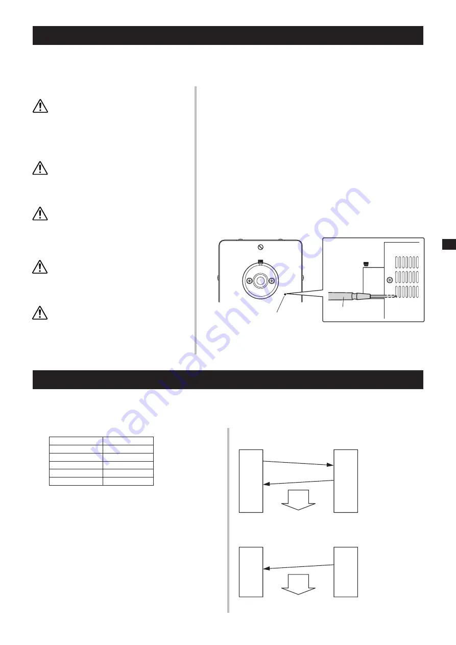
光出力調整ボリュウムの調整には、#00 の精密
ドライバを使用してください。

光出力調整ボリュウムは筐体表面の約 15  mm  奥
に位置します。ドライバを挿入する際は十分注意し
てください。

光量の調整は、確実にライトガイドを取り付け
てから実施してください。

ライトガイドを取り付けませんと、光量調整が正常
にできません。また、ライトガイドがない状態で
誤ってシャッターを開けますと強力な紫外線が出射
され、視力障害を起こすおそれがあります。

■  プログラムの設定方法

プログラムの設定方法およびオートモードでの使用手順は 15 ページと同様です。

光出力調整ボリュウム

精密ドライバ(#00)

Summary of Contents for LIGHTINGCURE LC8

Page 1: ...e unless this manual has been fully understood The person responsible for the equipment must not let anyone operate the equipment who does not have full understanding of the equipment Keep this manual...

Page 2: ...2...

Page 3: ...29 Adjustment of Optical Feedback Unit Option 32 Command Control 32 Contents of this manual are subject to change without prior notice Copying or quoting of this manual whether partially or as a whol...

Page 4: ...APAN INPUT 100 V 240 V 300 VA 50 HZ 60 Hz IOIOI S N DB0000 MODEL L9588 01 SPOT LIGHT SOURCE MADE IN JAPAN INPUT 100 V 240 V 300 VA 50 HZ 60 Hz CN1 AC IOIOI Component Names L9566 L9566 series L9566 Fro...

Page 5: ...connector page 32 oCooling fan 0Name plate position 1AC inlet 2Air inlets 3Light output adjusting screw page 32 zAlarm indicator page 24 xLamp ON indicator page 29 cLamp Operation time page 27 vRelati...

Page 6: ...6 1 1 1 2 JIS C 7550 3 JIS T 8141 30 kV 15 1 MPa 10 4 MPa 40...

Page 7: ...7 56 1 3 L9566 L9588 03 04 06A L9566 L9588 01A 02A 4000 L8253 3000 4000 L8253 3000 4000 L8253 3000 0 1 MPa 1 MPa IEC I ON OFF...

Page 8: ...8 25 80 10 cm 10 cm L9566 L9588 10 cm 10 cm 10 cm 10 cm...

Page 9: ...V 1 k GND 15 D sub w i GND ON o 4 GND ON 0 5 ON D sub 15P XM3A 1521 XM2S 1511 GND ON 50 V 30 mA GND ON ON 30 V 50 mA 100 1 k 50 V No 1 12 V 12 V dc 100 mA max 2 4000 L8253 3000 3 4 5 5 6 7 8 9 10 0 5...

Page 10: ...10 SHUTTER ERR LAMP ERR LAMP ERR UP DOWN LAMP ERR OVER HEAT 2 4000 L8253 3000 LAMP CHANGE 5000 q w 10 cm OFF OFF 10 cm...

Page 11: ...11 q OFF w e 1 MPa 10 r t y u...

Page 12: ...12 Save Normal POWER SAVING Save Normal POWER SAVING Normal Save 10 q w M4 8 e r LIGHTNING CURE LC8 A9616 10 q w e r q r M3 2 w e L9588 L9566 M3...

Page 13: ...13 0 1 MPa 1 MPa ON OFF ON OFF 10 q 15 w OFF e r t y 11 r u 4000 L8253 3000 LAMP CHANGE 5000 SHIFT UP DOWN OPERATING TIME UP DOWN 0 5000 10 OFF 30 ms 1 OFF 10 2 5...

Page 14: ...14 LAMP ON OFF 1 1 5 0 5 ON e ON 3 19 5 STABLE 5 r ON LAMP ON OFF 1 5 2 0 5 0 5 ON e r OFF 2 9 SHUTTER MANUAL 1 SHUTTER MANUAL 1 3 5 ON t ON 3 5 OFF t OFF...

Page 15: ...SELECT SHIFT SELECT SHIFT SELECT 3 w SHUTTER AUTO 7 7STEP 1 1STEP SHIFT SELECT W SHIFT 1STEP 1 W 3 1 7 STEP 7STEP 7 W 1 STEP 1 7 STEP 7 1 STEP 7STEP 1STEP 1STEP UP DOWN 0 100 1 SHUTTER MANUAL 0 00 W...

Page 16: ...16 1 2 7STEP SELECT 1 9 SELECT 1 2 1 P1 P2 P3 P4 P5 P7 P6 1 P1 P2 P3 P4 P5 P7 P6 1 2 1 UP DOWN 0 100 1 SHUTTER MAN UAL 0 00 W 4 50 W 0 02 W UP DOWN 0 1 999 9 0 1 2 1 2 0 0 3 6 7 3 1...

Page 17: ...SHIFT SELECT SHUTTER MANUAL r UP 3 LCD t SHIFT SELECT 3 SHUTTER MANUAL y SHUTTER MANUAL u i e t RS232C PC RS232C 1 9600 1 8 CR 0DH PC PC 1 INP 2 500 ms 50 ms 25 ms 20 ERR 1 PC ERR05 INP 2 ERR05 INP PC...

Page 18: ...xx L0OK L0NGxx S1OK S1NGxx S0OK ATOK ATNG03 AT ATSOK ATSNGxx ATT INT OK INT NG INT INT INTSETOK INTSETNGxx CURE OK CURE NG CURE nnn mmm m CURE n nn mmm m START OK START NGxx STP STOPOK INP LIFOK LAMPC...

Page 19: ...19 4000 L8253 3000 4000 L8253 3000 56 LAMP ERR UV 5000 PC 5 typ 11 11 13 13 11 17 18 13 15 16 10 11 11 15 14 14 17 17 17 10 17 PC 5...

Page 20: ...operation of the equipment Never look directly into the light guide connection aper ture or at the light emanating from the light guide Strong ultraviolet light can cause visual disorder DO NOT allow...

Page 21: ...orized When it is used and disposed of in any place outside of Japan it should be treated properly according to the statutory regulations of the state and local governments applicable to that place La...

Page 22: ...ended environment for use About 25 C ambient temperature 80 or less humidity Allow for adequate ventilation of fan exhaust Some lamps depending on types produce ozone which smells for some time after...

Page 23: ...g as it is inputted When no signal is inputted the shutter closes 14 Output intensity DOWN When this signal is inputted while the shutter is open using the manual mode the output intensity reduces as...

Page 24: ...ndicator flashes The unit can be used for some time after this indi cator starts flashing replace the lamp with a new one as soon as possible After replacing the lamp be sure to reset the accu mulated...

Page 25: ...he lamp flange so that the slit faces up as shown in the figure and push in the lamp as it is y After inserting the lamp fully align the groove in the lamp fixing cap and the pin of the lamp holder an...

Page 26: ...to install a specified filter A9616 series to a unit of LIGHTING CURE LC8 series Filter Installation Be sure to disconnect the power cord when installing the filter Do not install the filter while the...

Page 27: ...amp with a new one as soon as possible Also when the accumulated lamp operation time reach es 5000 hours the lamp is forced to turn off for the sake of safety Unless the accumulated lamp operation tim...

Page 28: ...the power failure time is 30 ms or less The lamp remains on Everything functions normally When the power failure time is about 1 second The lamp goes off and both of the lamp ON signal and lamp stable...

Page 29: ...flash for ap proximately 5 seconds If a panel button is pressed while the indicator lamp is flashing both the lamp and the indicator lamp go out The lamp does not go out unless the button is pressed t...

Page 30: ...and select the mode using the SELECT button As the program mode once set is stored in the memory of the main unit the program starts in the previously set mode when the power is turned on next time U...

Page 31: ...ty changes in steps Step 1 Output intensity setting display Adjust the output intensity diaphragm opening using UP and DOWN but tons 0 to 100 by every 1 When the optical feedback func tion is at work...

Page 32: ...seconds or longer to exit the PROGRAM mode and press the SHUTTER MANUAL button to close the shutter y Press the MANUAL button of the shutter to open the shutter u Using a precision screwdriver turn th...

Page 33: ...mory cure operation at work 02 If memory cure operation is at work it is terminated closed If auto cure operation is at work it is terminated closed NG auto function being executed 03 NG auto function...

Page 34: ...ce the lamp with a new one Adjust the intensity Wipe the end faces of the light guide clean with a gauze soaked with alcohol Tighten the lamp fixing cap securely Lower output intensity setting value o...

Page 35: ...35 1 1 1 2 IEC 2006 IEC 62471 EMI 30kV 15 1MPa 10 4MPa 40...

Page 36: ...36 56 1 3 4000 L8253 3000 4000 L8253 3000 4000 L8253 3000 0 1MPa 1MPa IEC I ON OFF L9566 L9588 03 04 06A L9566 L9588 01A 02A...

Page 37: ...37 L9566 L9588 10cm 10cm 10cm 10cm 25 80 10cm 10cm...

Page 38: ...GND D sub 15P XM3A 1521 XM2S 1511 50V 100 GND 1k GND ON 50V 30mA GND 30V 50mA 100 1k No 1 12 V 12V dc 100 mA max 2 4000 L8253 3000 3 4 5 5 6 7 8 9 UP 10 0 5 11 0 5 12 0 5 13 14 DOWN 15 GND COM w i GN...

Page 39: ...39 SHUTTER ERR LAMP ERR LAMP ERR UP DOWN LAMP ERR OVER HEAT 2 4000 L8253 3000 LAMP CHANGE 5000 q w 10cm OFF OFF 10cm...

Page 40: ...40 q OFF w e r t y 1MPa 10 u...

Page 41: ...41 Save Normal POWER SAVING Save Normal POWER SAVING Normal Save 10 q w M4 8 e r LIGHTNING CURE LC8 A9616 10 q w e r L9566 L9588 q r w e M3 2 M3 e...

Page 42: ...42 0 1MPa 1MPa ON OFF ON OFF 10 q 15 w OFF e r t y 40 r u 4000 L8253 3000 LAMP CHANGE 5000 SHIFT UP DOWN OPERATING TIME UP DOWN 0 1 1 5000 30ms 1 OFF 10 2 5...

Page 43: ...43 1 5 0 5 e ON 1 LAMP ON OFF 3 48 5 STABLE 5 r ON 1 LAMP ON OFF 5 2 0 5 0 5 e r OFF 2 9 2 1 SHUTTER MANUAL 1 SHUTTER MANUAL 3 5 t ON 3 5 t OFF...

Page 44: ...SELECT SHIFT SELECT SHIFT SELECT 3 w SHUTTER AUTO 7 7STEP 1 1STEP SHIFT SELECT W 1STEP 1 W 7 STEP 7STEP 7 W 1 STEP 1 7 STEP 7 1 STEP 7STEP 1STEP 1STEP SHIFT 7STEP 3 1 UP DOWN 0 100 1 SHUTTER MANUAL 0...

Page 45: ...45 1 2 SELECT 1 9 SELECT 1 2 1 P1 P2 P3 P4 P5 P7 P6 1 1 P1 P2 P3 P4 P5 P7 P6 2 1 2 1 2 0 0 3 6 7 3 1 1 UP DOWN 0 100 1 SHUTTER MANUAL 0 00W 4 50W 0 02W UP DOWN 0 1 999 9 0 1...

Page 46: ...00ms 50ms 25ms 20 ERR 1 PC ERR05 INP Fig 2 ERR05 INP PC PC PC ERR05 INP q w UV e SHIFT SELECT SHUT TER MANUAL r UP 3 LCD t SHIFT SELECT 3 SHUTTER MANUAL y SHUTTER MANUAL u UV i 3 5 00 UV UV 00 15mm 44...

Page 47: ...NTSETNGxx NG 03 CURE nnn mmm m CUREE nn n mmm m 1 2 W 1 9 1 or 2 1 2 W nnn n nn W mmm m s 7 CURE OK CURE NG NG 02 CURE CURE nnn mmm m CUREE n nn mmm m 1 9 1 or 2 1 2 W nnn n nn W mmm m s 7 START START...

Page 48: ...48 56 4000 L8253 3000 4000 L8253 3000 40 5000 40 42 42 40 PC PC 46 47 42 44 45 39 40 LAMP ERR 40 46 5 43 43 UV 5 46 46 46 39 46...

Page 49: ...10 seconds later more than 1 sec The initial state is resumed Ultravi olet leakage Not above 0 001 mW cm2 at 365 nm Paint Standard paint color used at HAMAMATSU PHOTON ICS Displays Back side printed f...

Page 50: ...V 240 V 300 VA 50 HZ 60 Hz IOIOI 142 110 16 16 227 5 311 232 39 5 39 5 36 12 7 49 49 158 49 49 311 232 39 5 39 5 36 12 7 142 110 16 16 227 5 158 S N DB0000 MODEL L9588 01 SPOT LIGHT SOURCE MADE IN JAP...

Page 51: ...9616 11 2 230 250 60 248nm Accessories Option Specifications of filters 50 5 123 118 3 mm UNIT mm mm A9616 A9616 series A9616 mm UNIT mm mm 8 7 55 53 7 27 5 68 2 46 Filter Type Number of Transmittance...

Page 52: ...1 50 million times of shutter operation Shutter Unit Optical Feedback 365 nm E9793 02 50 million times of shutter operation or 20 000 h Shutter Unit Optical Feedback 436 nm E9793 03 50 million times o...

Page 53: ...service life such as lamp shutter and relay specified by each manu facturer has expired The extent of the warranty shall be limited to delivery of a sub stitute unit The warranty period of the substit...

Page 54: ...54...

Page 55: ...55...

Page 56: ...gerstr 10 D 82211 Herrsching am Ammersee Germany Telephone 49 8152 375 0 Fax 49 8152 2658 E mail info hamamatsu de Denmark Office Lautruphoj 1 3 DK 2750 Ballerup Denmark Telephone 45 70 20 93 69 Fax 4...

Reviews: