10
It is always a good idea to go back to Step 5 and retake the data to confirm the alignment. After confirming the alignment,
click
Report
for a report of the entire alignment.
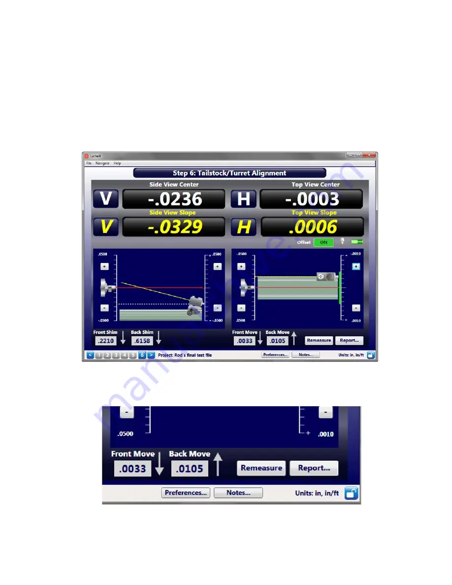
Step 6 – Tailstock/Turret Alignment Live Move Screen
After taking the spindle alignment data in Step 5, click
Next
to go to the Tailstock/Turret Live Move Screen. In this
screen, the mounting errors collected from Step 5 are applied as an offset to the data displays, showing the actual
alignment in four axes: Side View, showing the Vertical Center and Vertical Angle and Top View, showing the
Horizontal Center and Horizontal Angle.
The data is live and on-screen graphics illustrate either the tailstock or turret spindle alignment relative to the
headstock's spindle axis (AOR). Shim and Move values are also calculated to fix the alignment. The displays turn red
when the alignment is out of the tolerance selected in Step 1 or green if in tolerance.
Add the shim and spacers or make the horizontal move, watching the display update as you make each move. When the
displays turn green, it's aligned!


